This code is a flash loader for the Texas Instruments TMS570LS0914PGE SoC. Once this code has been loaded to to system over JTAG, the N2HET co-processor is used as an UART that prompts the user over a serial line and uses the YModem protocol to upload and download software to the SoC.
The code is based on sample code supplied by TI and described in the boot loader description found here, except the valid flag and all logic around validating the application image in flash has been removed by request.
In this context a flash loader is the code that runs on the micro controller while a host loader is a program on an external computer, communicating with it to download new code into flash.
Only the serial version is present here, while TI also provides spi and can bus
versions.
When built and installed with TI's Code Composer Studio on a micro controller
it can be used to load a new application into flash memory over a serial port
using a host loader that can use the ymodem protocol to send and receive
files. One such host loader is the pyMicroloader
that has already been updated to work with this flash loader.
It is also possible to interact directly with the flash loader by connecting a
USB-Serial adapter to the CON_TX and CON_RX pins on the rt-ihu. A prompt pin
is also used to stop the flash loader from executing a valid program in flash and
prompt the user with a menu instead as described below. The prompt pin on the rt-ihu
is ATTACHED.
If the the prompt pin (HET1 pin 8) is set to high and the MCU is
rebooted, a prompt $ , will be presented on the the serial port and the flash
loader will wait for a single character command. By responding with ? the following
menu will be shown
================== Main Menu ==========================
  1. Download an Application Image To the Internal Flash
  2. Upload the Application Image From the Internal Flash
  3. Execute the Application Code
  4. Get Flash Loader Version
  5. Get Device Information
  6. Application Status
  7. Select Run target
  8. Soft reset
  ?. Show this menu
=======================================================
The first choice will have the flash loader enter ymodem receive mode and wait for
a binary image file to be downloaded by the host. Ymodem will start sending a series of
C characters asking for CRC mode checksums on the 1k packets coming from the host. The ymodem protocol has been verified to work correctly with both the common
Unix sz programs and a Python version used by the host loader.
The flash loader expects a single file to be sent from the host.
Choice number 2 will attempt to send the application image from the MCU to the host
computer over the serial port using ymodem. Again this has been tested with the same
programs as the download. A script that uses the rb program from the Unix sz suite
to receive the application can be as simple as:
#!/usr/bin/env bash

DEV=/dev/ttyUSB0

stty -F $DEV 115200
rb >$DEV <$DEV
The MCU will send the program under the name UploadedApplicationImage.bin and it
has been used to verify that the whole ymodem transmission works, by comparing
the uploaded code with the binary file that was transmitted, byte for byte.
If an application has successfully been downloaded, hitting a 3 will start its
execution. The flash loader checks its memory block for the pattern 5A5A5A5A,
that is written to flash on the conclusion of a successful download operation.
If the pattern is not found, i.e. because no program has been downloaded, nothing
happens when this option is selected.
Option 4 simply prints out the version of the flash loader:
Flash Loader TI: 1.3.0
Previous version 1.0.0 implemented the application validation logic.Version 1.1.0 accidentally removed the run target logic which is brought back here in this version. Version 1.3 fixes a hang if the file we are trying to upload is too big, and also sends NULs on startup to avoid occasional garbage output when using the N2HET.
The output from option 5 looks like:
DEV:           8046AD1D
LOT NUM:       00B6E020
WAFER LOC NUM: 0000502B
FLASH START:   00010000
FLASH END:     00100000
The flash start address excludes the flash loader itself. The application must be linked to start at the 64K address (0x10000).
Option 6 shows the following information about the application, if loaded:
Run target value set to: 0x00000000, Unknown
Prompt pin is active
After removing the application validation, no address information is available.
The status of the prompt pin can also be seen on this output. The idea is to connect
this GIO input pin to the Vcc pin on the USB-Serial adapter from the host computer
and thereby have the flash loader go to prompt mode after the next reboot when
a host is connected regardless of the validity of the stored application.
This option allows for setting the value of the run target in SRAM.
Hitting 7 repeatedly will cycle trough the available run targets.
Run target value set to: 0x55555555, Flash loader
Run target value set to: 0xAAAAAAAA, Application
Run target value set to: 0x00000000, Unknown
The run target together with the status of the GPIO-pin connected to the USB-Serial interface will allow for bypassing the flash loader on reset as shown below, when a valid application is in flash.
| GPIO | Target pattern | Jump to |
|---|---|---|
| Low | 0x55555555 | Loader |
| Low | 0xaaaaaaaa | Application |
| Low | 0x00000000 | Application |
| High | 0x55555555 | Loader |
| High | 0xaaaaaaaa | Application |
| High | 0x00000000 | Loader |
The flash loader itself lives at the bottom of the flash memory starting with
0x20 (8x32 bits) for interrupt vectors followed by the boot loader code. The
application area starts at flash address 0x10000 (64k).
After boot the flash loader is entered, as it occupies the low memory of flash. The flash loader jumps to the application start offset, which in turn shifts all interrupts to the application handlers. The application will therefore handle all interrupts until the processor is rebooted and the cycle is repeated.
This in turn means that the application must be set to run in that address.
This code has been developed using the TI multi-platform, Eclipse based Code Composer Studio. Parts of the code has been generated with the Windows only HALCoGen code generator. Still another part must be assembled by the TI HET environment, again only available on Windows!
This directory contains code that is generated by the Windows-only HALCoGen program. This code should not be edited directly.
This directory contains the proper flash loader code.
Execution starts from loader_main() that is called
from the generated main() function in halcogen/source/sys_main.c
This directory contains the TI Flash Library used to actually write the code to flash (from RAM).
If needed the whole halcogen directory can be copied to a Windows machine
to (if Code Composer Studio is not running on a Windows machine). The setup
for this application is described below, assuming all the files have been
copied across and FlashLoader.hcg has been opened in the GUI program.
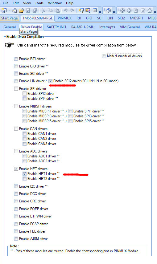
For this application only two drivers need to be enabled:
The SCI2 driver is used if a regular serial port is used, but HET1 if
the N2HET is used instead.
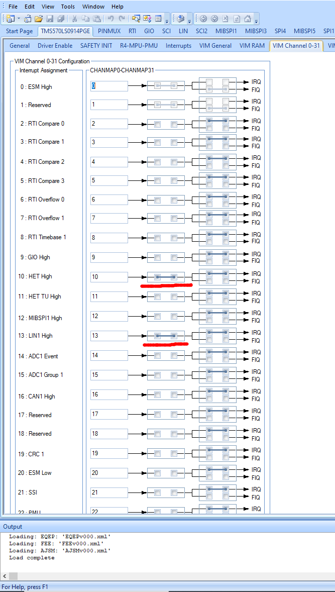
For this application we need to enable interrupt 10 and 13 and they should
be set as IRQ, not FIQ. This will in turn cause HALCoGen to generate
empty service routines for these interrupts.
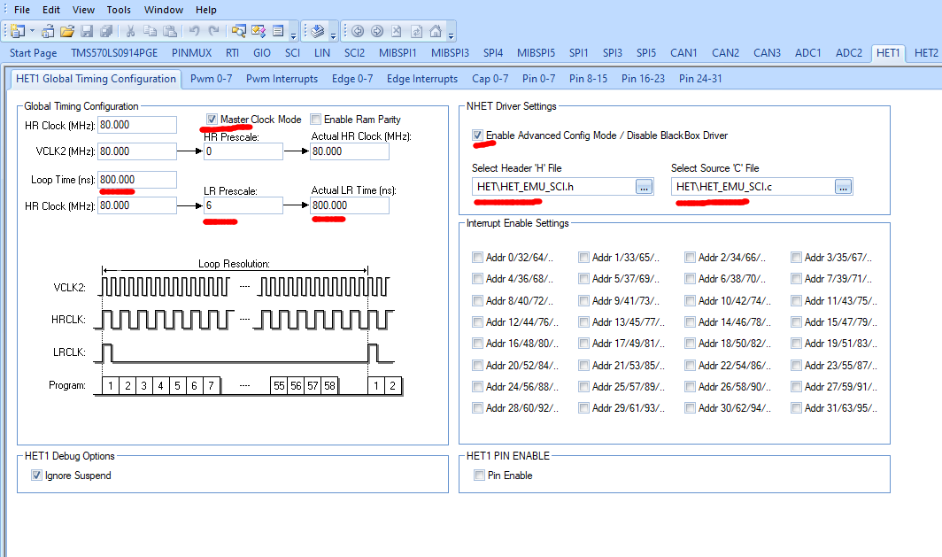
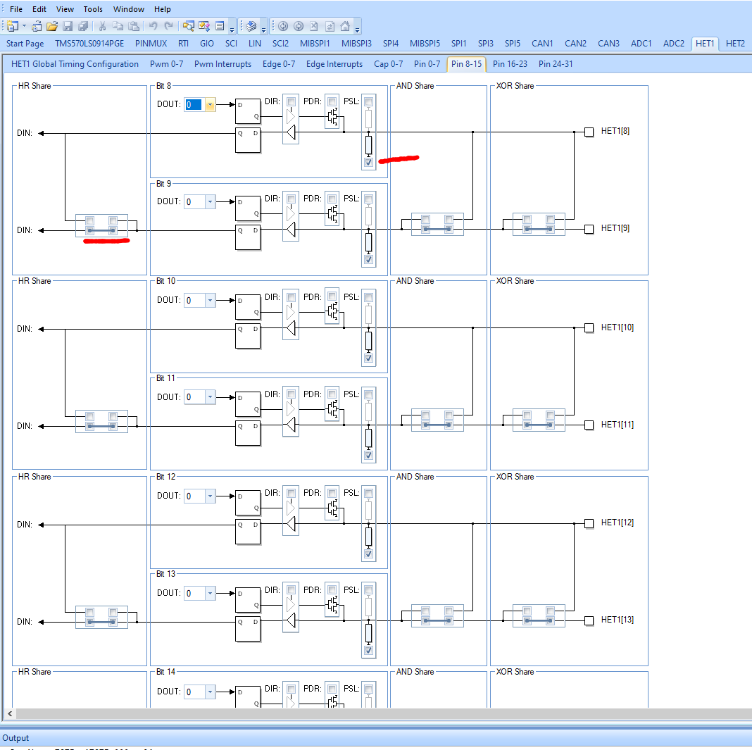
Make sure that all the marked fields in the screenshot below are set.
The header and source files have been generated from the .het assembler
file and are residing in the HET directory on the same level as the
HALCoGen source and include directories. These files are copied by the
tool into its own structure.
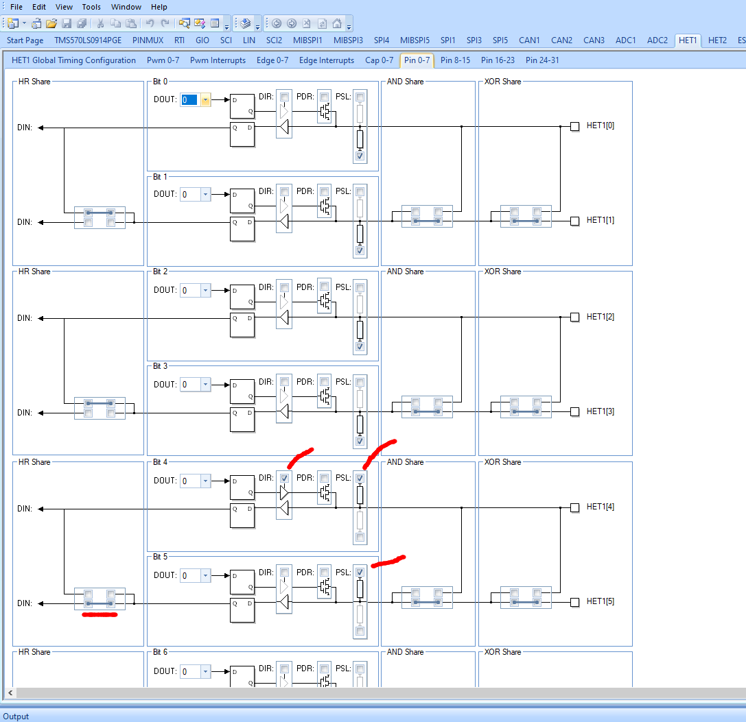
These pins are used for Tx and Rx in the UART respectively. Make sure direction of pin 4 is output and it has a pull up active. For pin 5 also have pull up, but keep it as input (the default). Also make sure that pin 4 is not looped back to pin 5 (default!).
This pin is used as prompt pin and connected to Vcc from the USB-serial interface to force the flash loader into prompting with a menu. Make sure that it is pulled down and not looped back to pin 9.
The HET_EMU_SCI.het assembler source file has already been compiled into .c and .h files
and can be used directly by HALCoGen as described above.
In case the .het file needs to be changed, the files need to be generated again.
The best way to do that is to run the assemble command. This command
assumes that HET tool has been installed and its \bin directory added to PATH.
For a detailed description of exception handling between the Flashloader and the loaded application see the Exception Handling document
There are two details required by the AMSAT RT-IHU satellite on-board computer. One is mentioned above and called the prompt pin. On Golf, this is called the Attached line, which is high when there is an umbilical attached. When the umbilical is attached, this loader will be started and will be ready to load new code. In space there will never be an umbilical attached, and thus this loader will jump directly to the application code.
In addition, the RT-IHU includes a watchdog. The code running in the RT-IHU must toggle the watchdog reset pin (aka kick the watchdog) at least every few milliseconds or the processor will reset. The pin for the watchdog reset is SPI1 (when set up as a GIO) pin 1. The watchdog chip has ignores resets that are too often so it might be that in some cases, the loader would kick the watchdog too quickly. Thus the flash loader has the capability of skipping resets based on the processor's RTI counter. However that adds code and uses additional chip capabilities, so it can be turned off by not defining WATCHDOG_TIMED_WAIT in bl_config.h.
