A plugin for Abaqus to define periodic boundary conditions to 3D geometry
The latest version can be downloaded from the Releases.
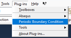
To install, copy all the .py files to your Abaqus plugin directory. When done correctly, the plugin should appear in Abaqus CAE under the plugins item on the menu ribbon:
Periodic boundary conditions can be used to model an infinite or semi-infinite domain using its unit cell. See this paper for more details.
In summary, a periodic boundary condition between two surfaces can be added in Abaqus by applying a relevant constraint between each of their nodes. This plugin allows to easily add periodic boundary conditions to an Abaqus model.
Before using the plugin to apply the periodic boundary condition, the following prerequisites are required:
- The two surfaces need to be defined as a surface on the part
- The two surfaces need to be meshed
- If any exempts are to be defined, these should defined in specific sets
When launching the plugin from the menu bar, the following dialog window will show up:
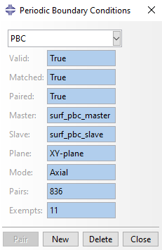
This gives an overview of all Periodic Boundary Conditions which are applied in the current model, as well as their status. After selecting any item from the dropdown menu, the following data will be displayed in the text fields:
- Valid: If this is False, it means that the master and slave surfaces do not have an equal amount of nodes, it is impossible to continue. An invalid Periodic Boundary Condition can be removed by clicking the Delete button.
- Matched: This indicates if each of the nodes of the slave surface has been matched with one of the nodes of the master surface. At this point, no modifications have been made to the mdb yet.
- Paired: This indicates if the constraints have been applied as sets and equations in the mdb. If this is True, the paired nodes should be highlighted with yellow circles in the 'Interaction' Module of Abaqus CAE. If this is False, the nodes can be paired by clicking the 'Pair' Button
- The Master and Slave indicates the name of the master and the slave surfaces.
- The pairs gives the amount of node pairs for the current Periodic Boundary Constraint.
The buttons, from left to right, are used to:
- Pair the currently selected periodic boundary condition
- Create a new periodic boundary condition
- Delete the currently selected periodic boundary condition
- Close the window
After clicking the 'New' button, the following window appears:
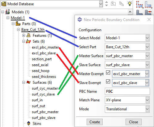
The user interface consists of the following items:
- Select Model: select the relevant model (usually you will only have one active model, which will be "Model-1")
- Select the part: select the relevant part on which the two surfaces are defined
- Select the master surface: this lists all the surfaces defined on the chosen part
- Select the slave surface: this also lists all the surfaces defined on the chosen part
- Select the set to exempt from the master surface, all nodes in these set will be ignored while matching and pairing nodes. This can, for instance, be used for edges which would otherwise be overconstrained due to another boundary condition on a neighbourinig face (by unchecking the box, no exemptions will be made).
- Select the set to exempt from the slave surface, all nodes in these set will be ignored while matching and pairing nodes. This can, for instance, be used for edges which would otherwise be overconstrained due to another boundary condition on a neighbourinig face (by unchecking the box, no exemptions will be made).
- PBC Name: the plugin will create sets and equation constraints for each node, this name will be used to identify them
- Match plane: the plane over which the periodic symmetry should be defined (this should be parallel with the two planes, but is not required)
- Symmetry: the symmetry to use for the component normal to the match plane
The two buttons will invoke the following:
- Create button: once a valid combination of inputs are selected (different master and slave surfaces and name defined), this button will become enabled and can be clicked to define the constraints
- Close button: can be clicked at any time to close the dialog window, no changes will be made to the model.
The plugin will try to match the relevant nodes between the two surfaces. If the two surfaces do not contain an equal amount of nodes, the code will abort without making any changes to the model and an error message will be printed in the console.
The code will try to match nodes with their exact coordinates, and in case this is not possible, the closest node will be searched instead. A confirmation dialog with statistics on this will be displayed, for instance:
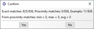
This means that out of 1338 nodes, 1247 exact matches were found and 91 were matched based on the closest node. From the latter 91 node pairs, the minimum destance was 2.40E-15 mm, the maximum 1.60E-3 mm, and the average 3.60E-5 mm. Since, in this case, the nodes are spaced with an average of 0.1 mm, this is considered acceptable.
In case the node matching is deemed acceptable, one can click the 'Yes' button after which the program will continue to pair the nodes.
In case the node pairing is deemed unacceptable, one can click the 'No' button, and the program will apply any constraints to the mdb. The new entry will appear on the overview dialog with False as the 'Paired' status. It is possible to pair the nodes anyway, or delete the constraint in order to alter the mesh, for instand by applying meshing rules which force the meshes to be equal should be implemented.
Before pairing the nodes, the code will not apply any modifications to the mdb. By pairing matched node pairs, individual sets are created by the code, which are then used to apply constraints to the mdb under the form of equations. These modifications will be undone when a Periodic Boundary Condition with paired nodes is deleted from the Overview dialog.
The constraints in the chosen match plane will be applied such that the displacements in the plane of both nodes in each pair are equal. For instance for the XY-plane, this would be:
Ux_1 - Ux_2 = 0
Uy_1 - Uy_2 = 0
For the constraints normal to the match plane, one can choose between three options:
- Asymmetric
- Symmetric
- Ignore
An asymmetric constraint (left) will apply equal displacements to each node pair, similar as to the in-plane directions, while a symmetric constraint (right) will apply displacements in the opposite direction. Applying an asymmetric constraint loses symmetry of the domain, but conserves compliance of the repetitive unit cell. A symmetric constraint does the opposite, this is illustrated in the figure below. By choosing ignore, no constraints will be added in the normal direction, and it is up to the user to define these. Which type of symmetry should be chosen is up to the user, in some cases (such as uniaxial tension), asymmetric symmetry will lead to rigid body motion instead of deformation, while in others it leads to absurd results (such as torsion + tension).

Currently the plugin suffers from the following limitations:
- The surfaces for the periodic boundary conditions must be defined on the same part: if your model contains periodic symmetry between surfaces on different parts, these must be merged into one part first. In case this is not possible, the plugin can not be applied.
- The plugin only works for 3D geometries, the plugin can not be applied for 2D geometries
- The plugin only allows periodic symmetry in the x-, y- and z-directions, therefore the model should be built or rotated in order to have the periodic planes parallel to one of the base planes. In case this is impossible, the plugin can not be applied