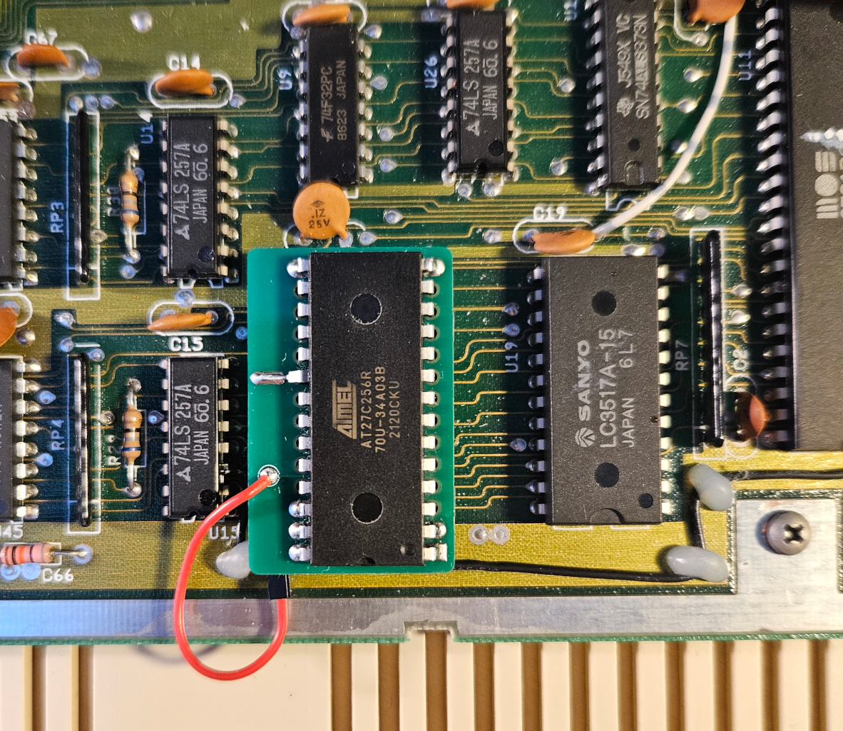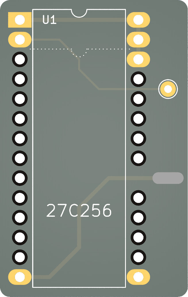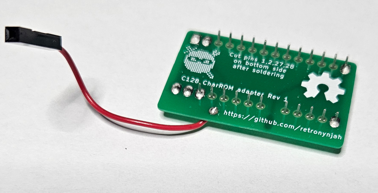
This is a recreation of the original character ROM adapter used with 27128 EPROMs in localized versions of the C128.
It doesn't add any functionality and it doesn't deal with any of the quirks of the original adapter.
The character ROM socket in the original C128 (non CR/DCR versions) was designed for 24-pin 2364 mask ROMs. When localized C128 versions were made, Commodore didn't make new mask ROMs for all the localized character ROMs. Instead they used a regular 2764 or 27128 EPROM on an EPROM adapter. The location on the motherboard under the bottom edge of the keyboard means there is no room for bulky EPROM adapters. This was solved using a thin adapter PCB that sits between the 27128 and the ROM socket. Many pins share the same locations on 2364 ROMs and 2764 EPROMs so all the pins of the EPROM except five goes straight through the adapter and into the ROM socket meaning that the adapter adds extremely little (if any) height compared to a chip without adapter. There are however some differences in the pin-outs and one of the biggest complications with this arrangement is that pin 23 of the EPROM (A11) goes into pin 21 (A12) of the ROM socket while pin 2 (A12) of the EPROM is left hanging outside the socket. This was then connected to the A11 signal on the motherboard instead using an external cable so A11 goes to A12 and vice versa. Swapping the A11 and A12 pins also meant the charset layout had to be rearranged on the EPROM to come come out correctly when read by the C128.
Another thing that needed handling was pin 18 (CE) of the 2764 EPROM which could't be inserted into the ROM socket where it would have ended up at A11.
This pin was bent out and connected directly to ground. This was fine because 27xx EPROMs have two select lines (CE & OE) and the other select line alignes correctly with CE in the ROM socket so the chip would still be selected properly.
Pin 26 (NC or A13) was inserted into VCC in the ROM socket and pins 1 (VPP), 27 (PGM) and 28 (VCC) were all connected to Pin 26 (VCC) on the adapter. This means that any 2764/27128/27256/27512 EPROM can be used with the adapter if the character data is duplicated or is placed in the highest 8kB of the EPROM. I like to use modern AT27C256R EPROMs.
Side by side comparion of 2364 ROM and 27128 EPROM illustrating address pin conflicts
Thanks to Jani for insights and discussions and for his documentation about the original adapter which you can find at https://blog.worldofjani.com/?p=4614
There are gerber files in the gerbers directory.
The recommended PCB thickness is 0.6mm. Not because a 1.6mm board won't fit in the computer but because it leaves one more millimeter of the EPROM pins exposed so it sits better in the socket.
The order of the character banks needs to be arranged in a special way so you can't just grab any character ROM image when burning the EPROM. The computer expects to find the character sets in this order:
- US characters (uppercase/petscii)
- US characters (lowercase/uppercase)
- National characters (uppercase/petscii)
- National characters (lowercase/uppercase)
But because A12 and A11 have switched places the character sets must be arranged in the following order in the EPROM to work with the adapter:
- US characters (uppercase/petscii)
- National characters (uppercase/petscii)
- US characters (lowercase/uppercase)
- National characters (lowercase/uppercase)
- Program the EPROM with a compatible ROM image.
- Bend out pin 20 of the EPROM.
- Insert the EPROM in the adapter and align the notch with the marking on the board.
- Solder all the pins that have solder pads from the top side of the PCB to avoid adding too much solder to the bottom. This makes the adapter sit more flush in the socket. Pin 15 doesn't have to be soldered but it adds some rigidity to the adapter which can flex a bit otherwise.
- Cut or bend away the external pins 1, 2, 27, 28 so that they won't touch anything when installing the adapter.
- Solder pin 20 to ground by pushing it down against the PCB and solder it to the special pad.
- Solder one end of a short cable (6 centimeters) to the single throughole on the adapter.
- Solder the other end of the cable to the via close to pin 22 of the ROM socket. I'm using a dupont cable and soldering a header pin to the via for easy removal.

