What is the Correct Way to Install the 40-Pin Header and the Screen?
biergaizi opened this issue · 2 comments
Hello.
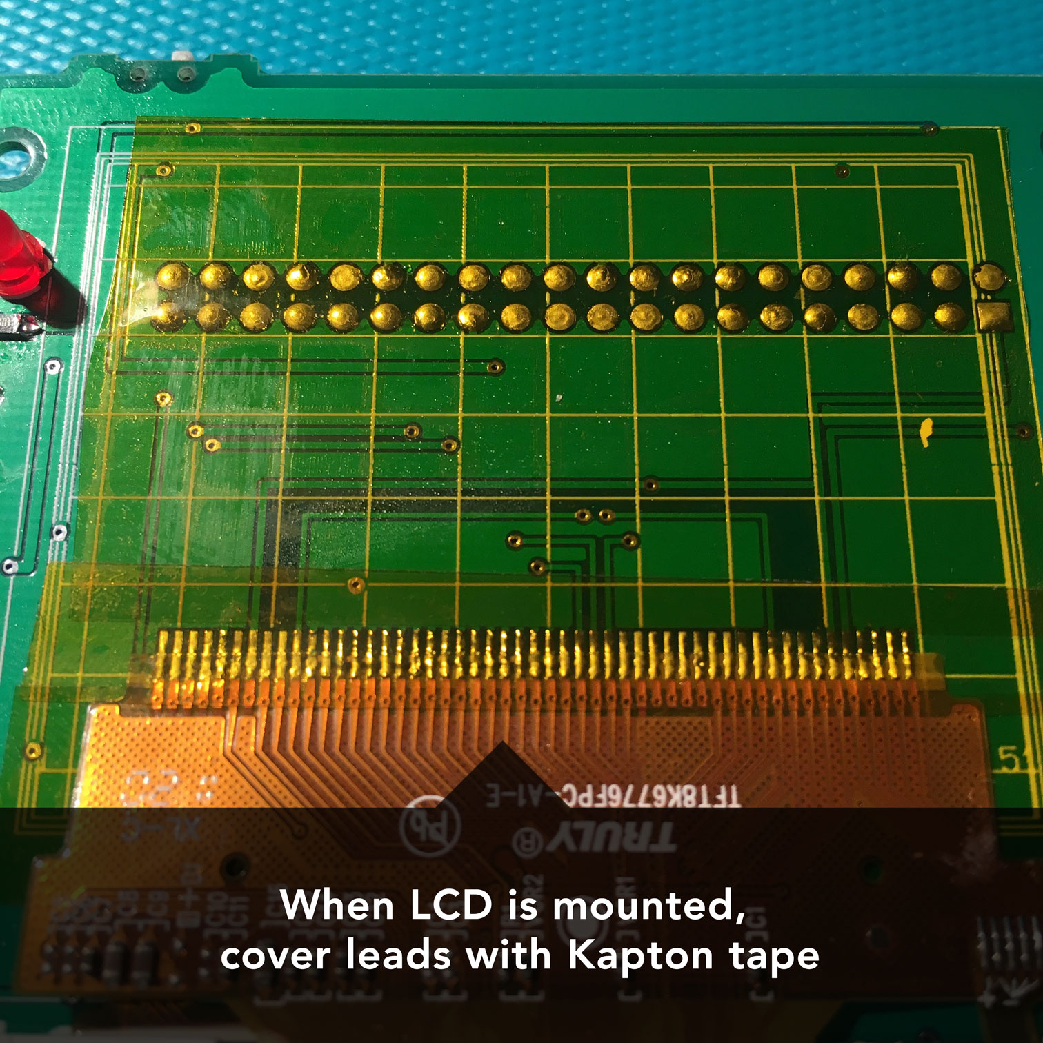
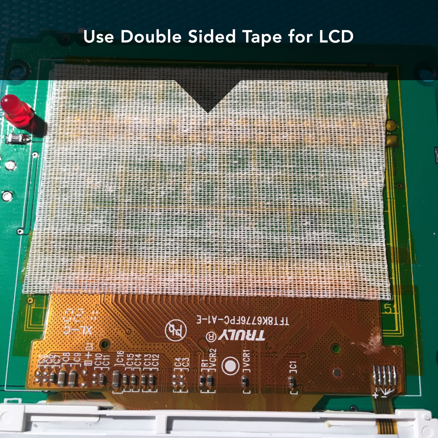
I finally started to assemble the board. I was able to install all the components and the system booted successfully. But I found I've soldered the pin header directly, and the pins would penetrate to the other side of the board, together with the solder joints, the screen is impossible to fit on the board, so it's not possible to install the board inside the enclosure. I've read through all the resources about GabozePocaio, but it seems none of them mentioned how to solder the 40-Pin header for the Raspberry Pi mount.
I tried to use a wire-cutter but I found the exposed pins were too short to cut, I also tried to grind the pins out using a Dremel, but I found it's very easy to damage the solder mask in this process. Currently my result of the experiment is three dead boards.
My questions are:
-
What is the correct way to install the header and the screen? Is the pin header in the project BOM a non-standard low-profile version, or is there a special method used here to install it? I've reviewed the spec of TLW-120-06-T-D and I didn't find anything special, so I just used a generic pin header in my toolbox, is it possible that I've missed something?
-
How is the screen installed on the board? How is the proper clearance possible to achieve despite the solder joints between the board and the screen? None of the picture shows what's behind the screen.
Thanks again for creating this cool project.
Awesome, thanks!


