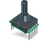
This library provides support for the Bourns EAW - Absolute Contacting Encoder (ACE)
Datasheet: https://www.bourns.com/pdfs/ace.pdf
This is a small 8 bit gray code rotary position sensor providing 128 unique positions. It manages this with a single encoder track with 8 contacts spaced evenly around it.
This is a "digital knob" you can use to control your arduino project. It can also be used in motion control systems with a limited lifespan.
This code is developed against the Arduino UNO R3. It should work on any Arduino.
The code currently supports the MCP23008, PCF8574 and PCF8574A I2C expanders
Select these with the following addresses
- 0x00 - 0x07 MCP23008 addresses 0x20-0x27. (This is backward compatible with an earlier library revision)
- 0x20 - 0x27 PCF8574
- 0x38 - 0x3F PCF8574A
Note that the MCP23008 and PCF8574 chips use the same i2c address range. Many LCD backpacks also use one of these chips. Be careful when mixing all this on the same bus to avoid duplicating addresses. To confuse things further, raw I2C addresses have the lowest order bit as a read/write signal, so some documents, like some of the PCF8574 datasheets, will refer to 0x40 and 0x70 which is 0x20 and 0x38 shifted left one bit.
You can also connect the ACE128 sensor directly to 8 Arduino pins, with an alternate constructor.
This library now conforms to the library manager standard, so it needs no special instructions here. See https://www.arduino.cc/en/Guide/Libraries
The enclosed exmple sketch ACE128test drives a 2x16 display via either and I2C backpack or direct from the Arduino, depending on whether you comment out the LCD_I2C macro.
ACE128testpins tests the bare sensor connected to Arduino pins. The common pins on the sensor should be connected to ground.
  // user-accessible "public" interface
  public:
    // constructor takes i2caddr (see above) and pointer to PROGMEM map table
    // example: ACE128 myACE((uint8_t)0, (uint8_t*)encoderMap_12345678);
    // see make_encodermap example sketch for alternate pin mappings
    ACE128(uint8_t i2caddr, uint8_t *map);
    ACE128(uint8_t i2caddr, uint8_t *map, int16_t eeAddr);
    // direct pin constructors are similar but instead of the I2C address, you list the 8 arduino pins used
    ACE128(uint8_t pin0, uint8_t pin1, uint8_t pin2, uint8_t pin3, uint8_t pin4, uint8_t pin5, uint8_t pin6, uint8_t pin7, uint8_t *map);
    ACE128(uint8_t pin0, uint8_t pin1, uint8_t pin2, uint8_t pin3, uint8_t pin4, uint8_t pin5, uint8_t pin6, uint8_t pin7, uint8_t *map, int16_t eeAddr);
    void begin();                  // initializes IO expander or Arduino pins, call from setup()
    uint8_t upos();                // returns logical position 0 -> 127
    int8_t pos();                  // returns logical position -64 -> +63
    int16_t mpos();                // returns multiturn position -32768 -> +32767
    void setMpos(int16_t mPos);    // sets current position to multiturn value - also changes zero
    void setZero();                // sets logical zero to current position
    void setZero(uint8_t rawPos);  // sets logical zero position
    uint8_t getZero();             // returns logical zero position
    uint8_t rawPos();              // returns raw mechanical position
    uint8_t acePins();             // returns gray code inputs
void reverse(boolean reverse); // set counter-clockwise operationSee the ACE128test and ACE128testpins examples.
- Include all the encoder maps you need (see below) to match the pin sequences of your ACE units.
- Declare all your ACE128 objects using the ACE128 constructor. It takes an I2C address and a pointer to the encoder map. An optional third integer can take a positive integer to show where to store zero info in eeprom. Allow for three bytes.
- call the begin method for each ACE128 object from setup(). This will use the eeprom settings or fall back to setting the current position as zero.
- The pos() and upos() methods return the position relative to a logical zero position rather than the zero position returned by the encoder, which is in a mechanically arbitrary spot. When it rolls over the turns are stored for use by mpos and saved in eeprom
- Once per loop(), call pos(), upos(), or mpos() and store the value in a variable. Accessing i2c bus takes some cycles, so don't call pos() everytime you want to refer to it.
- there are three setting functions
- setZero() - set the current location to zero (does not update multiturn)
- setZero(int) - sets the zero point to the 0-127 number given
- setMpos(int) - sets the current location as this multiturn value
This library comes with various encoder maps to permit different wiring of the pins between the ACE and the IO expander. These are generated by the included make_encodermap example sketch. To generate a custom encoder map:
- edit the make_encodermap sketch
- change the pinOrder array to match your wiring
- change the pinString to match your wiring
- load the sketch to the Arduino
- copy the serial monitor output to a new .h file in the ACE128 folder.
12345678 is for the "rising counter clockwise" wiring, which matches the datasheet numbers and is recommended for breadboard testing. When breadboarding, remember the pins on the sensor are numbered anticlockwise as viewed from above.
comments and feedback via https://github.com/arielnh56/ACE128
more details and videos at https://www.tindie.com/products/arielnh56/high-resolution-absolute-encoder-128-positions/
buy assembled units at https://www.tindie.com/products/arielnh56/digital-knob-for-arduino-i2c-absolute-encoder/