The ALPINE M-BUS is a protocol for the remote control of CD changers used in car audio systems. The purpose of this project is to emulate or pretend the presence of a CD changer to the head-unit to enable the external audio input, tweaking the buttons for other applications or showing data on the display.
As the audio signal coming from the CD changer is only turned on (un-muted) by the amplifier if the CD changer has replied to the commands coming from the head-unit, it is NOT possible to connect an MP3 player or other auxiliary audio signal from outside the radio without interfacing the M-BUS controller. This is where our project comes into play here: The software decodes the M-BUS commands and emulates the functions of the CD changer/player by sending processed messages (frames) back to the head-unit.
- All major commands supported: playing, skipping, resuming, disk changing, repeat, scan, etc..
- M-BUS protocol timings generated/measured by accurate 16bit timer
- Current status and information display on HD44780 LCD
- Debug output on UART/serial console
- Commented & cleaned code, hardware tested on 7525R head-unit
- For own mp3 players or just for fun...
Get a local copy of the repository with git clone https://github.com/picohari/atmega128_alpine-mbus-emulator.git or simply download the zip archive.
Check your avr-gcc -v, it should be similar to mine:
Using built-in specs.
COLLECT_GCC=avr-gcc
COLLECT_LTO_WRAPPER=/usr/local/avr/libexec/gcc/avr/4.8.5/lto-wrapper
Target: avr
Configured with: ../configure --target=avr --prefix=/usr/local/avr --disable-nsl
--enable-languages=c,c++ --disable-libssp
Thread model: single
gcc version 4.8.5 (GCC)
Compile the code by running the makefile with make
On my board the external crystal oscillator has 16Mhz, the timing parameters in the code have been adjusted to match this value. Final tuning was made with logic analyzer.
To program the AVR and set fuses I prefer the USBasp.
Run avrdude -cusbasp -pm128 -Uflash:w:main.hex to flash the firmware onto the controller.
The code was written for our little friend, the ATmega128 microprocessor from ATMEL and compiled with GCC! The sources for the decoding and encoding routines originates from the well known and ever copied since: http://www.hohensohn.info/mbus/
Some minor changes have been made to the state-machine based communication control routine and to the ISR receiving code, but the software is still in development...
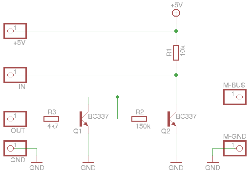
Due to the different voltages between head-unit and the AVR controller, a very small piece of hardware is required to perform level adaptation. With my gear, the original schematic from hohensohn.info didn't work for me, so I took a different level shifting circuit.
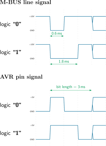
The M-BUS is kind of pulse-width modulation: A logical "0" is transmitted as a 0.6ms long pulse and a logical "1" is about 1.8ms
Here we can see the transmission of the PING command on the left side and the reply on the right side. The signals have been already inverted and converted to 5V for the controller pins. M-BUS IN is the signal injected by the AVR to the head-unit. M-BUS OUT is the signal coming from the head-unit.
We read:
| Address | Command | Checksum |
|---|---|---|
| 0 0 0 1 | 1 0 0 0 | 1 0 1 0 |
| 0x01 | 0x08 | 0x0A |
and later the reply (self-decoding on the input line):
| Address | Command | Checksum |
|---|---|---|
| 1 0 0 1 | 1 0 0 0 | 0 0 1 0 |
| 0x09 | 0x08 | 0x02 |
Ping - Pong!
The voltage on the M-Bus is about 10V and drops off very quickly if the load is too high. During my tests, the solution with the Z-Diode didn't work, so I took two small signal NPN transistors to do the level shifting:
The signals generated by the microcontroller [OUT] are inverted: a logic "1" (5V) on the output pin pulls down LOW the line on the bus through Q1. A logic "0" will keep it HIGH by the internal pull-up resistor in the head-unit.
If the bus line goes LOW and the beginning of a logic "1" is signalled by the falling edge, R1 pulls the level on the receiving pin [IN] to HIGH and the ISR is triggered.
On the AVR ATmega128 pin PD4 is used as input for receiving packets (Input Capture Pin Timer 1: ICP1) and PD5 is configured as output pin to drive the bus line LOW.
A simple breadboard setup is done in less than 10 minutes. I like very much the ET-BASE boards from ETT (http://www.ett.co.th/product/03000AVR.html) for development and this is how looks like:
Not much to say, look at the source code. The playing of a CD is emulated by Timer2. Timer1 capture reads the incoming packets and Timer0 is used for sending. I've refactored the original sources and removed this ugly-looking hungarian notation to get some cleaner plain C - it's still not yet completed and leaks further commenting, ...
I will do some more measurements on the timing and include screenshots of the logic analyzer. More to come.
- Fork it!
- Create your feature branch:
git checkout -b my-new-feature - Commit your changes:
git commit -am 'Add some feature' - Push to the branch:
git push origin my-new-feature - Submit a pull request :D
TODO: Write history
http://www.hohensohn.info/mbus/ https://github.com/kjanesch/pseudochanger
See LICENCE.md file


