UART data degrades when reading long data strings when connected to Arduino
Tiogaplanet opened this issue · 30 comments
I have been trying to read data from the MiP using an ATmega328P connected via UART. For short queries the UART connection works fine. I can read the volume level out of the MiP, for example. But when I try to read longer data strings from the UART the answer falls apart with each read. I send a 0x14 and get a 0x14 back. after that I get 30 and 45 (for an ASCII 0E, or year "14") but after that I start getting weird results like 9A and 8A for the month, values that are obviously not ASCII encoded. The two bytes I read for the day part of the version number are even worse and actually change with each time I try to read the software version number. I've tried all kinds of different delay values between reads. I've tried resetting the MiP and the Arduino. I've sped up and slowed down the baud rate. I'm pretty sure at this point that the UART port just isn't a reliable method of communicating with the MiP. Any insight?
I'm using an ATmega328 at 3.3V/8MHz. I just realized that configuration can't reliably communicate at 115200 baud. Is there a way to decrease the MiP's UART baud? I don't see that in the documentation.
Hi Tiogaplanet,
It does sound like baud rate unsync.
Are you using 8MHz internal resistance or crystal?
And are you using a hardware or software UART?
I was using the SparkFun MiP ProMini Pack which has an external crystal for 8MHz. I am using hardware UART. I am waiting for a ATmega328@5V/16MHz to arrive in the mail and I think it will solve the problem I'm experiencing but in the meantime I would like to know if there is something I can do to decrease baud rate on the MiP UART.
Thank you.
@Tiogaplanet It looks like the SparkFun MiP ProtoMini Pack has a select line which you need to pull high before you can send or receive data from the MiP. When I look at your code here, I don't see that select line being held high while you are reading out all of the bytes. I do see that it is held high here while sending the command. If it took almost 5 milliseconds for the MiP to start responding then you could be switching the UART mux back over to the FTDI cable before the MiP even finished responding.
It would be best to keep the select line high from the time you start sending the serial data to the MiP until you receive all of the response data back from it. I also wouldn't try sending any debug output while you had that select line high either as it would go to the MiP and not to your PC terminal. Store away the data that you receive in a buffer and at the end, drop the select line low and then send out any debug output that you want.
@adamgreen I very much appreciate your input as I've seen the work you've put into your own libraries. I'll keep your comments in mind as I await the arrival of an ATmega328p@5V/16MHz. I'm pretty convinced at this point that the problem lies in the fact that the UART of the MiP only operates at 115200 and the 3.3V/8MHz ATmega just cannot perform reliably at that speed without employing some kind of hack.
I await the arrival of an ATmega328p@5V/16MHz
On a related note, is it ok to use 5V signal levels with the MiP UART pins? I seem to remember the MiP uC running at 3.3V. If so, I am not sure that its UART pins are 5V tolerant.
@adamgreen I very much appreciate your input as I've seen the work you've put into your own libraries.
Thanks! I have always meant to update it with a version which could connect an ARM Cortex-M microcontroller to the UART directly like you are doing here but I have never gotten around to it.
On a related note, is it ok to use 5V signal levels with the MiP UART pins? I seem to remember the MiP uC running at 3.3V. If so, I am not sure that its UART pins are 5V tolerant.
Yes, I intend to use a voltage divider circuit to drop the 5V UART signal down to the MiP's 3.3V.
@Tiogaplanet Looks like you have your bases covered then :)
By the way, I saw this thread on AVR Freaks which seems to indicate that you might also have 115200 bps problems, even at 16MHz with the AVR.
@adamgreen Well, I read that thread and it's pretty depressing! I'll give it the old college try and if it doesn't work out I'll use my pro mini boards for something else. I was really hoping to get these Arduino boards to talk to the MiP.
I spent all day at work thinking about your suggestions above. I know I tried similar things before but it's been awhile so I figured I shouldn't rely on memory and try again. I tried your ideas as soon as I got home but it didn't seem to change things at all.
void setup() {
  pinMode(2, OUTPUT);
  Serial.begin(115200);
  digitalWrite(2, HIGH);
  delay(5);
  Serial.write(0xFF);
  digitalWrite(2, LOW);
  delay(500); //Need a delay to let the buffer clear

  uint8_t swver_array[] = {0x14};
  getSoftwareVersion(swver_array, 1);
}

void loop() {
  // put your main code here, to run repeatedly.

}

int8_t getSoftwareVersion(unsigned char *message, uint8_t array_length) {
  digitalWrite(2, HIGH);
  delay(5);
  uint8_t i = 0;
  for (i; i < array_length; i++) {
    Serial.write(message[i]);
  }
  delay(500);
  uint8_t data_array[10];
  i = 0;
  int j = 0;
  Serial.println(Serial.available());
  while (Serial.available()) {
    data_array[i] = Serial.read();
    ++i;
    delay(1000);
  }
  digitalWrite(2, LOW);
  delay(5);

  while (j < i) {
    Serial.println(data_array[j], HEX);
    ++j;
  }

  return 0;
}
Produced these results:
31
34
30
45
30
A6
B2
30
E6
It's actually better than I've been getting but still not good enough.
It was worth a try. Sorry to hear that it didn't work!
If Sparkfun still sold those MiP boards, I would buy one and try some experiments here with it as well...including the replacement of the crystal if need be :)
@Tiogaplanet - I have taken Sparkfun's design files, ordered some PCBs from OSHPark, and ordered components from Digikey. I will put together one of those SparkFun MiP ProtoMini Pack boards myself when everything arrives to do some experimenting :)
@adamgreen That is awesome! This project could use someone smart like you working on it. I wish you the best of luck. I do this as a hobby - my day job is quite unrelated so I don't keep up the kind of proficiency I'd like to in coding and I'm certainly not able to take on building PCBs from design files.
@sailimc Any word on whether the MiP's UART can run at a lower speed than 115200?
@Tiogaplanet I don't know about smart but definitely up for a challenge :) I had always planned to do some microcontroller related stuff with the MiP but just never got around to it. This seems like a good project to fulfill that goal!
I ordered a 8MHz resonator like Sparkfun used and another @ 14.7456MHz which should generate a more accurate 115.2k bps signal. If I can get it to work, maybe I can ship you a modified board.
It will be a few weeks before I have everything here to start playing with it more.
@adamgreen I can solder but I don't think I solder well enough to replace a tiny surface mounted resonator.
I've been working on this on and off over the last two years. I can wait a few more weeks.
@Tiogaplanet Unfortunately there isn't a way to lower MiP's uart speed without modifying the mcu code. There is another trick you can try, try sending the command"0x01,0x02" for enabling hacker uart port and disabling BLE uart port before you send "0x14". Also might change your baud rate a little like "115000" or "115500" but I guess you already tried ?
I've been working on this on and off over the last two years. I can wait a few more weeks.
@Tiogaplanet - Hopefully the 16MHz board will work out for you even earlier. It will get you closer to the correct bit rate.
There is another trick you can try, try sending the command"0x01,0x02" for enabling hacker uart port and disabling BLE uart port before you send "0x14". Also might change your baud rate a little like "115000" or "115500" but I guess you already tried ?
I hadn't tried those things before. I tried last night but none of those things helped.
I was using the SparkFun MiP ProMini Pack which has an external crystal for 8MHz. I am using hardware UART. I am waiting for a ATmega328@5V/16MHz to arrive in the mail and I think it will solve the problem I'm experiencing but in the meantime I would like to know if there is something I can do to decrease baud rate on the MiP UART.
@Tiogaplanet Did you get your 16MHz board to test? If so, how did it work out for you?
I finished receiving all of the parts a week ago to make my own SparkFun MiP ProtoMini Pack. I soldered it up last week, attached it to my MiP and am almost ready to start reproducing the problem that you are seeing.
I have ordered a different FTDI dongle for programming it since I don't want to risk supplying 5V to VCC from the programming port when connected to the MiP and the new dongle I have ordered makes disconnecting VCC from the FTDI all together much easier. I could also cut off the VCC pin from the programming header on the PCB but it is convenient to have when testing with the PCB disconnected from the MiP. I should have the new FTDI dongle next week and then I will start experimenting.

I received my 16MHz part but only a couple days before going on vacation. It's sitting on my desk waiting for my return next week. Good luck to you!
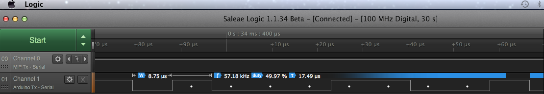
I reproduced this problem with my MiP as well. For informational purposes, here are some timings that I took with my logic analyzer of the SparkFun MiP ProMini Pack sending data and then the MiP responding.
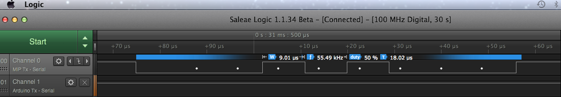
- The ProMini is using a bit time of 9.01us => 110,987.8 bps
- The MiP is using a bit time of 8.75us => 114,285.7 bps
- The correct time is 1/115200 = 8.68us.
- The difference between the MiP and ProMini is (9.01us - 8.75us) / 8.75us = 0.0297 = 2.97%
I wonder if the 16MHz board will work. I believe that the AVR will run a bit fast with a 16MHz resonator, 8.5usec bit time => 117,647 bps. That is a difference of (8.75us - 8.5us) / 8.75us = 2.86%
I have an idea of some other experiments to try. Keeping my fingers crossed.
I wired up a cable to connect the MiP to the 5V/16MHz pro mini and then realized I don't have the right FTDI basic breakout. I've got the 3.3V, not the 5V, and while I can modify it with a simple solder bridge I'd rather keep it 3.3V and buy a 5V one as well. So it will be a while longer before I can work on this some more.
I've got the 3.3V, not the 5V, and while I can modify it with a simple solder bridge I'd rather keep it 3.3V and buy a 5V one as well. So it will be a while longer before I can work on this some more.
Yeah, I hit pretty much the same issue. I ended up getting an Adafruit FTDI Friend, cutting the 5V power connection and adding a male header so that I could select Vcc to be one of the following:
- 3.3V
- 5V
- Unconnected
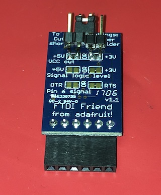
When I have the SparkFun MiP ProMini Pack installed in the MiP, I leave Vcc unconnected since it is getting power from the MiP's batteries anyway.
I built up a new ProMini Pack tonight and soldered down a 14.7456MHz resonator instead. This board is able to reliably receive data from the MiP at 115200.
The code I used:
// Pin used by the TS3USB221A switch to connect the AVR UART to the MiP or PC.
// Set to HIGH, it selects the MiP.
// Set to LOW, it selects the PC.
#define MIP_UART_SELECT_PIN 2


void setup()
{
  pinMode(MIP_UART_SELECT_PIN, OUTPUT);
  digitalWrite(MIP_UART_SELECT_PIN, LOW);
  Serial.begin(115200);

  // Send 0xFF to the MiP via UART to enable the UART communication channel in the MiP.
  const uint8_t initMipCommand[] = { 0xFF };
  sendMessage(initMipCommand, sizeof(initMipCommand));
  // The MiP UART documentation indicates that this delay is required after sending 0xFF.
  delay(30);
  Serial.print("MiP is Alive!\n");

  // Request the software version information from the MiP using command 0x14.
  const uint8_t getSoftwareVersionCommand[] = { 0x14 };
  sendMessage(getSoftwareVersionCommand, sizeof(getSoftwareVersionCommand));

  // Dump the returned data. It should be a hexadecimal representation of the data (2 ASCII characters per byte).
  uint8_t buffer[5*2];
  memset(buffer, ' ', sizeof(buffer));
  receiveData(buffer, sizeof(buffer));
  for (uint8_t i = 0 ; i < sizeof(buffer) ; i++)
  {
    Serial.write(buffer[i]);
  }
  Serial.write('\n');
}

void loop()
{
  // Request the MiP to make the burping sound.
  const uint8_t burpSoundCommand[5] = { 0x06, 0x02, 0x00, 105, 0x00 };

  Serial.print("Burp!!\n");
  sendMessage(burpSoundCommand, sizeof(burpSoundCommand));
  delay(5000);
}

void sendMessage(const uint8_t* pMessage, uint8_t length)
{
  // Wait for any queued data destined to the PC to be transmitted and then switch the TS3USB221A switch
  // to connect the AVR UART pins to the MiP.
  Serial.flush();
  digitalWrite(MIP_UART_SELECT_PIN, HIGH);

  // Send the specified bytes to the MiP via the UART.
  while (length-- > 0)
  {
    Serial.write(*pMessage++);
  }

  // Wait for that data to be transmitted and then set the TS3USB221A switch to connect the AVR UART pins back to
  // the PC connection.
  Serial.flush();
  digitalWrite(MIP_UART_SELECT_PIN, LOW);
}

void receiveData(uint8_t* pData, uint8_t length)
{
  // Wait for any queued data destined to the PC to be transmitted and then switch the TS3USB221A switch
  // to connect the AVR UART pins to the MiP.
  Serial.flush();
  digitalWrite(MIP_UART_SELECT_PIN, HIGH);

  // Read the data bytes from the MiP.
  Serial.readBytes(pData, length);

  // Set the TS3USB221A switch to connect the AVR UART pins back to the PC connection.
  digitalWrite(MIP_UART_SELECT_PIN, LOW);
}
The output generated by this program:
MiP is Alive!
140E031602
Burp!!
Burp!!
I am very interested to hear how your 16MHz test goes.
If your 16MHz is a success, we would have 3 possible modifications that could be made to the MiP ProMini Pack to make it work:
- Modify the board to run at 5V and use a 16MHz resonator.
- Modify the board to run at 5V and use a 14.7456MHz resonator (even multiple of 115200).
- Modify the board to use a 7.3728MHz resonator (even multiple of 115200). I think the dimensions are a little different and the solder pads will have to be modified accordingly.
I think it's working. I'm finally getting a repeatable and expected result when asking for the software version. I just need to fine-tune my convert from ASCII to decimal value. I'm using the Arduino Pro Mini at 16MHz, 5V.
Getting these results pretty consistent now. Thinking about putting it in a loop to make sure.
Software version: 45.33.46.32
I think it's working. I'm finally getting a repeatable and expected result when asking for the software version.
Awesome!
Software version: 45.33.46.32
Shouldn't the software version be something like 0E,03,16,02 which converts to a date-build of 2014_03_16-2?
If it is of any help, here is some code that I quickly threw together and tried on my desktop machine:
#include <assert.h>
#include <stdio.h>
#include <stdint.h>


size_t hexStringToBinaryData(uint8_t* pOutput, size_t outputSize, const char* pInput, size_t inputSize);
uint8_t hexDigitToNibble(char hexDigit);


int main(void)
{
    const char hexData[5*2] = "140E031602";
    size_t     parsedLength = 0;
    uint8_t    binaryData[5];

    parsedLength = hexStringToBinaryData(binaryData, sizeof(binaryData), hexData, sizeof(hexData));
    assert ( parsedLength == sizeof(binaryData) );

    printf("    hex: %.10s\n", hexData);
    printf(" binary: %02x %02x %02x %02x %02x\n",
           binaryData[0],
           binaryData[1],
           binaryData[2],
           binaryData[3],
           binaryData[4]);
    printf("version: %u%02u%02u-%u\n",
           2000 + binaryData[1],
           binaryData[2],
           binaryData[3],
           binaryData[4]);
    return 0;
}

size_t hexStringToBinaryData(uint8_t* pOutput, size_t outputSize, const char* pInput, size_t inputSize)
{
    // The binary version of the data is half as long as the hexadecimal representation.
    size_t outputLength = inputSize / 2;
    assert ( outputSize >= outputLength );

    // The hexadecimal representation needs to have an even length since it needs two hex digits per byte.
    assert ( (inputSize & 1) == 0 );

    while (inputSize > 0)
    {
        uint8_t currByte = 0;

        currByte = hexDigitToNibble(*pInput++) << 4;
        currByte |= hexDigitToNibble(*pInput++);
        *pOutput++ = currByte;
        inputSize -= 2;
    }

    return outputLength;
}

uint8_t hexDigitToNibble(char hexDigit)
{
    if (hexDigit >= '0' && hexDigit <= '9')
        return hexDigit - '0';
    else if (hexDigit >= 'A' && hexDigit <= 'F')
        return hexDigit - 'A' + 0xA;
    else if (hexDigit >= 'a' && hexDigit <= 'f')
        return hexDigit - 'a' + 0xa;

    // Only get here if the code encountered an invalid hex digit.
    assert ( 0 );
    return 0;
}
Gives following output:
    hex: 140E031602
 binary: 14 0e 03 16 02
version: 20140322-2
Great! Thank you very much, @adamgreen. My code isn't as pretty as yours but I'm finally getting the same results as you and I'm getting them consistently!
Software version: 14.3.22.2
I'm going to tidy things up a bit then commit to my repository which is a clone of the one from Sparkfun.
Still interested in your boards. What I have just won't look as pretty as the fitted boards that you have no matter what I do. I have a daughter-board to the Pro Mini that contains the divider circuit to match the 5V of the Pro Mini to the 3.3V of the MiP.


I'm finally getting the same results as you and I'm getting them consistently!
Software version: 14.3.22.2
That's awesome! Congrats!
Still interested in your boards. What I have just won't look as pretty as the fitted boards that you have no matter what I do. I have a daughter-board to the Pro Mini that contains the divider circuit to match the 5V of the Pro Mini to the 3.3V of the MiP.
Ok. Based on your findings, it seems like a 5V 16MHz version of the board is the way to go. When I get back in town, I will start working on that. Once I get it started, I will post a link in this issue to my new project so that we can continue the discussion over there.
Thanks!
Now testing a new 5V/16MHz version of the MiP ProMini Pack design from over here with a new more feature complete Arduino library.