This package localizes the lidar sensor in a given map using the ICP algorithm. It subscribes to lidar scans and it registers them in a given map. If provided, it can use odometry or IMU to extrapolate the pose between the two iterations of ICP.
The user should provide a reference map (point cloud) as as a .pcd file and an initial pose in the reference map.
Released under BSD 3-Clause license. Parts of the code in this repo have been inspired by the code inside google cartogrpaher. We've retained the copyright headers where applicable.
Author: Edo Jelavic
Maintainer: Edo Jelavic, jelavice@ethz.ch
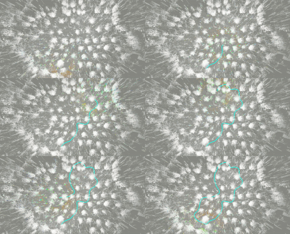
| localization in a forest | localization in an urban environment |
|---|---|
 |
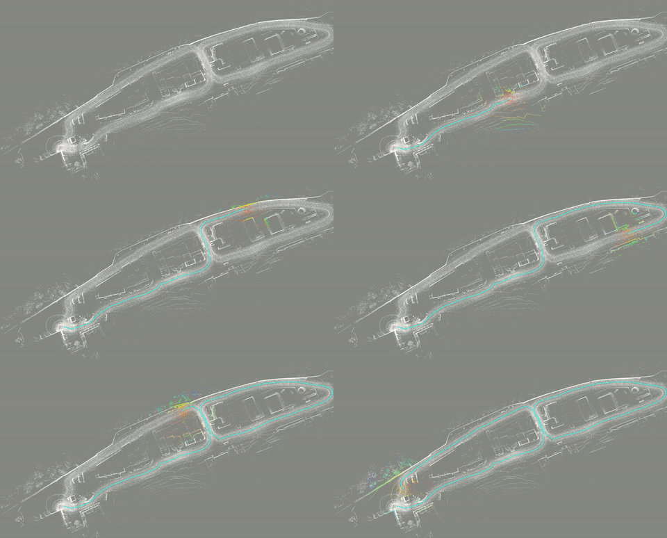 |
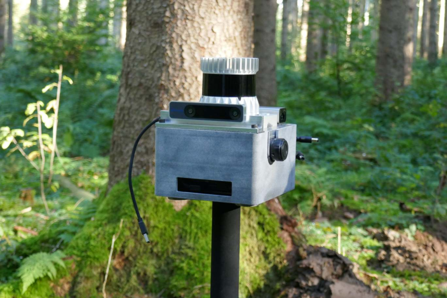
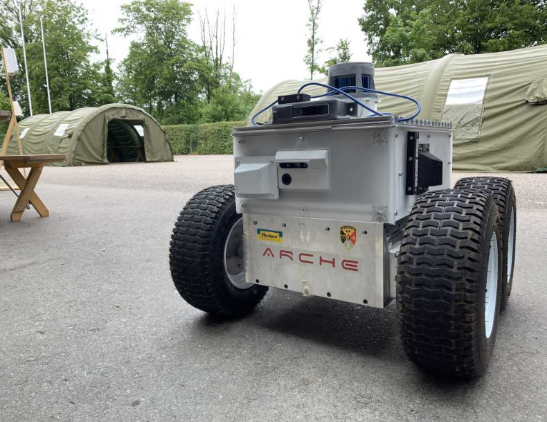
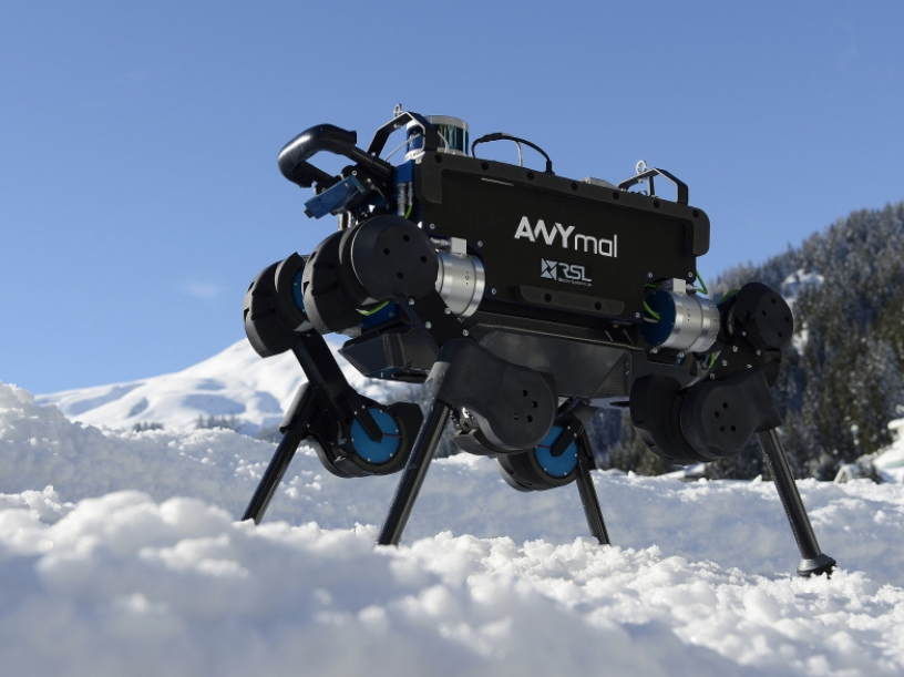
The package has been tested on the platforms shown in the images below. It has also been used during the ETH Robotic Summer School 2021 & 2022 (link). The corresponding launch files can be found here.
A corresponding map can for example be created using Open3D SLAM.
| handheld sensor module | skid steer robot | legged robot |
|---|---|---|
 |
 |
 |
Install ROS and library dependencies with:
sudo apt install -y ros-humble-pcl-ros ros-humble-pcl-conversions ros-humble-tf2-geometry libgoogle-glog-dev ros-humble-libpointmatcher
# OR, use rosdep in your source folder `src`
sudo rosdep install -yr --from-paths .
Build with:
colcon build --symlink-installRun with:
source install/setup.bash
ros2 launch icp_localization bringup.launch.pyThis package is based on the libpointmatcher package and it uses the ICP implementation from there. Libpointmatcher has an extensive documentation. icp_localization provides ROS wrappers and uses either odometry or IMU measurements to calculate initial guesses for the pointcloud alignment.
You can launch the program on the robot with: roslaunch icp_localization icp_node.launch. The pcd_filepath parameter in the launch file should point to the location where you stored your refrence map (pointcloud) in the .pcd format.
You can download the example bags and the example config files here. You can copy paste the rosbag and the map (.pcd file) to the data folder. Put the .yaml file in the config folder and you should be ready to run the forest environment example. For running the urban example, please adjust the parameters in the icp_node_rosbag.launch file. You need to chnage the pcd_filename, input_filters_config_name, bag_filename and the parameter_filepath.
The rosbag examples can be luaunched with roslaunch icp_localization icp_node_rosbag.launch
Note that the urban dataset uses the velodyne LIDAR whereas the forest dataset uses the ouster LIDAR. Please adjust the input_filters config file accordingly. Furthermore, in the forest dataset instead of full scans, each lidar packet is converted to pointcloud msg and then published.
The system has been tested with T265 tracking camera as an odometry source as well as legged odometry. If you are using the T265 make sure that you disable internal mapping and localization since it can cause pose jumps which will break the ICP.
The node also subscribes to the /initialpose topic and you can use rviz to set the initial pose of the range sensor. Note that this is not the initial robot pose since the range sensor coordinate frame might not coincide with the robot frame.
The node publishes the TF tree: map->odom->odom_source->range_sensor (in case you are using the odometry).
The configuration is split into three .yaml files.
The icp.yaml file configures the ICP settings such as error metric and outlier filters. Any filter that is applied to the map can also be defined here.
The input_filters.yaml file configures operations that are applied to each scan of the range sensors. Subsampling, cropping and normal computation are configured in this file. Two examples have been provided (one for the velodyne puck range sensor and the other one for the ouste OS1 sensor).
The filtering and the ICP can be configured by adding your own custom configuration .yaml files. Documentation on how to do that can be found here.
The rest of the parameters is explained below:
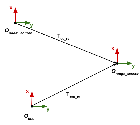
icp_localization/initial_pose- initial pose of the range sensor frame in the provided map.icp_localization/imu_data_topic- ROS topic on which the imu data is publishedicp_localization/odometry_data_topic- ROS topic on which the odometry data is publishedicp_localization/num_accumulated_range_data- Number of pointcloud messages that will be accumulated before trying to register them in a map. In case you are using full scans this parameter should be set to 1. In case you are publishing LIDAR packets, you need to convert them to sensor_msgs::Pointcloud2 first. At the moment there is no motion compensation implemented.icp_localization/range_data_topic- ROS topic on which the LIDAR data is publishedicp_localization/is_use_odometry- Whether to use odometry for initial pose prediction. If set the false, the pose extrapolator will try to use the imu data.icp_localization/is_provide_odom_frame- Whether to provide the odom frame or publish directly map to range sensor transformation onlyicp_localization/gravity_vector_filter_time_constant- Constant used for filtering imu measurements when estimating gravity. Smaller constant gives noisier estimates but adapts quicker to changes in orientation. Higher numbers give smoother estimates but take longer time to adapt to new orientation.icp_localization/fixed_frame- Fixed frame map. Used mostly for visualization.icp_localization/min_num_odom_msgs_before_ready- Ensure to have minimum number of msgs before starting ICP such that we can interpolate between them.calibration- calibration parameters between sensors. The coordinate frames are shown below. Tos_rs is a transoformation from odometry source (e.g. tracking camera) to the range sensor frame.Timu_rs is the transformaion form the imu to the range sensor frame.
All coordinate frames follow the URDF convention: http://wiki.ros.org/urdf/XML/joint.
