Minimize power consumption
Opened this issue · 155 comments
The current code is based on the SDK v3.1.1.2 lowPower beacon example, which seems to last on a coin cell for a couple/few weeks. There is also a git repo with a power optimized firmware here: https://github.com/ThuanLeUte/ble-st17h66_fw_power_consumption, and there might be other ideas to lower power consumption (like putting the chip in deep sleep and just wake up for a single broadcast every 5 sec).
First it's necessary to actually measure the power consumption of the different firmwares, and then start experimenting with the code to get it lower.
@vadimkozhin did you ever analyse the power draw with the rigol on your bench?
did you ever analyse the power draw with the rigol on your bench?
@biemster Yes. It is aligning with datasheet - 4.7mA during transmit. For now I can't get anything less from a chip, so I decided just plug in the new batt and leave it to check if it lasts more then a week...
So far it works from 16.08. It transmits once in 5 sec.
Thanks! Did you also measure the current when idle?
It is... the same. I've not done precise measurements, just watch it on my power supply. It jumps from 4.7 to 5.2 approx.
I hope I will be able to improve on that, since the tags I got usually had the battery in place, and were switched on by pressing the button. I guess those tags are lying on the shelf sometimes for a month or more, which would drain the battery in that case.
Yes, according to datasheet there is a sleep mode with less current, but it is deactivated only with a hardware pin e.g. with button preset.

There is (according to datasheet) couple of interesting options, but I cannot succeed to activate them, with provided SDK samples. Good luck with experiments! :)
Thinking about it, 5mA on a 230 mAh 2032 should only give you 40 hours of running, so I guess it is idling already on a lower power mode?
5mA on a 230 mAh 2032 should only give you 40 hours of running, so I guess it is idling already on a lower power mode?
Exactly my thoughts! So that's why I decided just plug in the battery and see what will happen after a week or two. So far it is on since 16.08, so yes, definitely idling. May be need to find a way to accurately measure a batt consumption.
I had to replace the battery in one of my tags already for the second time, so I'm getting about a month or so, give or take a week. That's shorter than I was hoping.. The 1uA sleep mode with RTC will be my goal, do you think the datasheet means with external RTC?
So I put in two fresh batteries when I opened this ticket, but they both seem to have died already 4 days ago. That puts it on just over two weeks with an advertisement every 3 seconds, which is a bit disappointing I must say.
Maybe I should prioritize this.
Mine is two months and still appears on the map. 8 sec interval. Will wait till it drain the battery.
Well done! I'll have to think out a way to accurately measure the power draw first. All I have at the moment is a basic multimeter from Lidl, I should be able to do better than that. Also the 2032s I'm using are not of the best quality, so my measurement could have been a bit biased.
@vadimkozhin do you by any chance know how long it takes the mcu to send out the advertisement packet?
do you by any chance know how long it takes the mcu to send out the advertisement packet?
Unfortunately not. The tag is "traveling" at the moment :) If you still will be interested in this interval, ping me in a week or so, then tag will be again in my hands and I can measure actual interval with oscilloscope.
I don't know if it's useful or not, but maybe looking at this project and asking @pvvx could give you some ideas: the battery lasts around 1 year. Looking at the datasheet the telink chip is more efficient (deep sleep 1uA with ram retention vs. 4uA for the st17h66, transmission 4.8mA vs 8.6mA) but OTOH it has to manage a display and the temperature/humidity sensor.
I've been eyeing that project for a while as well, especially since the 17h26 seems to be a clone of the telink used in those thermometers. @pvvx seems to be very able with such material, good idea to ask him for suggestions.
I didn't get good results with the available examples from the SDK for PHY62xx and AiThinker on PB-02-Kit modules (PHY6212).
The best example is with AT-BLE-UART:
Before the test, enter the commands:
AT+BLEMAC=234567123456
AT+BLEADVINTV=2560
AT+RST
reboot...
AT+SLEEP=0
Adv-Interval: 2560*0.625 = 1600 mc.
The result of measuring the current along the 3.3V line only to the module:
The current averaged over 140 seconds is 40.7 μA.

The current in sleep mode is about 19..20 uA, which is a lot.
Usually the sleep current is highly dependent on the software implementation and not on the directions in the datasheet...
Thanks @pvvx ! That's very useful info. With 40uA average you'd get 230 days out of a 230mAh button, that's considerably better than the two weeks I'm getting now, and it could even be stretched to a year with a longer adv interval.
I'm still thinking out how to do the power measurement, and get a nice plot like yours, without breaking the bank on new equipment. (although I could just take an interval of 10+ seconds, and measure the sleep current with my DM as well I just realize..)
I assume you made this plot with a scope?
With 40uA average you'd get 230 days out of a 230mAh button, that's considerably better than the two weeks I'm getting now, and it could even be stretched to a year with a longer adv interval.
These are very bad indicators.
For a key on a typical BLE SoC with advertisement every 3 seconds, the total average consumption should be less than 10 uA.
In active mode for most BLE SoCs (Telink, nRF, ERF):
wake-up (1..2 ms) and advertising transmission (2 ms) - average current 5..9 mA
In sleep mode with RTC and active 32 kilobytes of RAM - 2..3 uA.
( 7mA * 3ms + 0.003mA * 2997ms ) / 3000ms = 0.009997 mA = 10uA
I'm still thinking out how to do the power measurement, and get a nice plot like yours, without breaking the bank on new equipment. (although I could just take an interval of 10+ seconds, and measure the sleep current with my DM as well I just realize..) I assume you made this plot with a scope?
https://github.com/pvvx/UBIA/tree/master/PowerProfiler
For best sampling results (up to 50..100kHz):
GY-169(INA169) + oscilloscope https://aliexpress.con/item/4000107917726.html
or INA199 + oscilloscope
- Replace the shunt resistor with a switchable set with a maximum resistance of 100 ohms.
PS: Without PowerProfiler, there is no point in programming BLE.
Just ordered a GY-169 INA219
For a key on a typical BLE SoC with advertisement every 3 seconds, the total average consumption should be less than 10 uA.
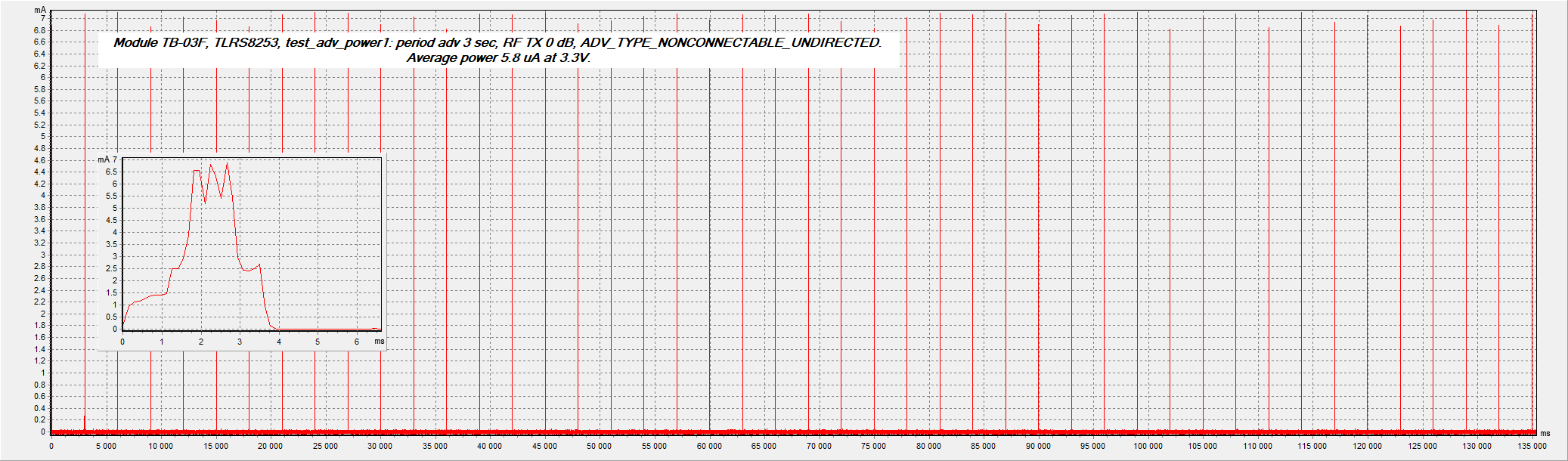
Module TB-03F, TLRS8253, test_adv_power1: period adv 3 sec, RF TX 0 dB, ADV_TYPE_NONCONNECTABLE_UNDIRECTED.
Average power 5.8 uA at 3.3V.
Module TB-03F, TLRS8253, test_adv_power3: period adv 3 sec, RF TX +3 dB, ADV_TYPE_NONCONNECTABLE_UNDIRECTED.
Average power 6.1 uA at 3.3V.

Those are great numbers @pvvx ! I should definitely target sub 10uA seeing those results.
With 40uA average you'd get 230 days out of a 230mAh button
The documentation for PHY62x2 does not indicate power consumption in sleep mode with active-retention RAM. And measurements with examples available in the SDK give disappointing readings - 10..20 uA, depending on the retention RAM size.
ST17H66B2 datasheet: 4uA @ Sleep Mode with 32KHz RTC and all SRAM retention

Not known which memory block has a specific leak in the sleep (0.6V).
This is more complicated than I thought. I was hoping there would just be a function in the SDK power manager to call, with an enum or so to specify the sleep mode.
What do you mean by "a memory block with a specific leak in the sleep (0.6V)"?
hal_pwrmgr_RAM_retention(RET_SRAM0|RET_SRAM1|RET_SRAM2);
hal_pwrmgr_RAM_retention(RET_SRAM0);
During sleep, the LDO switches to 0.6 V and the leakage currents to different SRAM blocks are different.
That seems to be present in the current code already on L140. I'm wondering why sleep is broken in this implementation, I hope the INA219 arrives soon and I can start experimenting.
I didn't get good results with the available examples from the SDK for PHY62xx and AiThinker on PB-02-Kit modules (PHY6212).
@pvvx There is a newer version of this SDK including the sources of rf.lib where some of the sleep code is located available here:
https://github.com/duanmubingshuai/test
Maybe those can help you get better results?
I tested on the PB-02-Kit by cutting the power wire of the module on the PCB.
But on other outputs of the module, leaks are possible...
A lot of consumption was due to taken examples from the SDK.
Rewriting everything to my version turned out better:

The reason for the high consumption of PHY6212:
- The program is placed in RAM. A large amount of RAM is constantly fed. Current in Sleep 5.6+ uA at 64KB.
- Long time to wake up the chip from sleep. From 2 ms to the start of transmission of advertising packets.
- If you don't change pGlobal_config[MAX_SLEEP_TIME] to a value greater than the advertising interval, the chip will unnecessarily wake up for a couple of ms and sleep again every cycle of the advertising interval. This leads to an increase in the average current consumption.
(There is a patch for GCC: https://github.com/biemster/st17h66_FindMy/blob/main/lib/rf/patch.c#L7712 )
This is PHY6212, and ST17H66 is most likely similar to PHY6252. ST17H66 and PHY6252 have a cache for executing code from FLASH. PHY6212 does not.
There are different SDKs for PHY6252 and PHY6212:
http://wiki.phyplusinc.com/doku.php?id=menu:sdk
PHY62XX SDK v3.1.1 (适用PHY6222/PHY6252)
PHY62XX SDK v2.1.1 (适用PHY6212)
PHY6252 used "section_xip_code" (LR_ROM_XIP 0x11020000 0x020000)
https://github.com/biemster/st17h66_FindMy/blob/main/FindMy/scatter_load.sct#L49
But there are no such sections for GCC: https://github.com/biemster/st17h66_FindMy/blob/main/FindMy/RTE/Device/ARMCM0/phy6202.ld
Got my INA219 today! I don't have an STM32 or TLSR lying around so I can't use the PowerProfiler directly, but I have some ESP's, pico's and arduinos to spare so I'm confident I can build something workable. @pvvx 's repo is a great resource for this, so it shouldn't be long!
So now I read the INA219 inputs have a bias current of 20 uA, making measurements at that level very inaccurate :(
I guess it's back to the drawing board then..
I should have listened better to @pvvx and buy an INA169 which has an input bias current of 10 uA, although how much of a difference would that make?
The INA199 has an input bias current of 28 uA, even worse than my 219.
On the other hand the INA326 has an input bias current of 2 nA (nano!), but I can't find any modules from my favorite overseas supplier. Wait that's not a power monitor.
Any suggestions are more than welcome!
The input bias current depends on the voltage at the common inputs. It is stable at a stable temperature and is subtracted from the measurements... Use a zero calibration for each shunt and supply voltage.
(INA228/INA229 - 20 bits, Input bias current: 2.5 nA (maximum).)
Power Profiler is needed not for measuring the average total current, but for debugging with the aim of obtaining the lowest currents using a visual diagram of work. It is possible to measure the SoC sleep current with a simple tester. And to measure the current during activity - no. The average current is the sum of these currents over time.
INA169, INA180, INA199 can be used to connect an oscilloscope. The oscilloscope measures the average current over a short active cycle window. Knowing this current and the time of the measurement window of the active cycle, add the current in the sleep pause and get the average current.
If you need a turnkey solution, then there is a more or less option for the price and quality of nRF Power Profiler Kit 2.
A professional absolute measurement solution with the required dynamic range costs more than a few hundred thousand dollars :)
thanks for that explanation @pvvx ! Good to know that those input bias currents can be calibrated out, I'm going forward then with this setup. Unfortunately I don't have an oscilloscope on my bench due to budget constraints, so a turnkey solution is even more out of reach :(
I have a DM here capable of uA measurements, so the plan now is to have the chip sleep for 10+ seconds and measure the power draw with that, and then make the diagram with the INA219 and scale the output so it matches the sleep current measured with the DM.
Guys, just to inform you, my setup still working from August 16.
Guys, just to inform you, my setup still working from August 16.
That's amazing! I have quite a few drain on me already, to a point I'm not putting batteries in anymore. I'm still trying to find time to do the power measurement, seeing yours is still running is encouraging!
@biemster I forgot to mention one, may be important thing -- I am completely remove the buzzer from the board. And just for the info, beacon time interval in my example was set to 8000.
good point about the buzzer, as it is connected to uart which is active. I'll keep that in mind when I start on this (hopefully during the holidays), I just need to desolder the shunt on my INA219 and calibrate it so it shouldn't be that much work
Here are the measurements I made on my Lenze st17h66 beacon flashed with @biemster's latest FindMy firmware (commit 5633d40 on Sep 6, 2022) using the NORDIC Power Profiler Kit II:

The average consumption is ~234.47uA @ 3V (spikes are every ~3.127s).
It is 30 times more than to the nRF51822 FindMy beacons I have tested (234uA vs 7.60uA), so I think there is a great margin for improvement... Tell me if I can help with additional measurements.
that's great work @sebi5361 ! I noticed my batteries draining quite fast as well, this confirms that. I'm on holiday atm so i can't work on this for a couple days, but I'm definitely going to ask you to run this test again a couple of times on some new versions of the code, if you are willing. thanks!
Happy to help!
@sebi5361 from your measurements, what is the power draw while the chip is sleeping? and how many milliseconds do those peaks last? (I'm trying to figure out where most energy is spent, should i optimize the sleep or the peaks)
@biemster: I will give you the exact values pretty soon but you should start by optimizing the sleep...
Indeed the average consumption is close to the sleep consumption (horizontal blue line on the graph is close to 234uA) currently.
Idle
224uA * 3.12s = 700uC

Emission
6.4mA * 4.6ms = 30uC
Note the 3 similar emission spikes.

Conclusion
700uC vs 30uC = 23 times more reasons to spend time on idle rather than emission at the moment.
3 peaks is a typical transmission of BLE advertising over 3 channels.
Problems only in the first 2 ms. But this is an invariable part - this is the wake-up time of this SoC. A small optimization is possible, by a few percent, but this is already related to the internal algorithms in the SDK implementation.
Sleep consumption is atypical for this SoC. Something is set incorrectly. Most likely GPIO pull-ups or internal controllers are not disabled.
Originally posted by @vadimkozhin in #7 (comment)
@biemster I forgot to mention one, may be important thing -- I am completely remove the buzzer from the board.
For what reason might the buzzer be leaking some current?
Is it the same for the LED?
Should I remove both to perform additional tests?
Pictures of Lenze st17h66 round beacon:
| Front | Back |
|---|---|
 |
 |
For what reason might the buzzer be leaking some current? Is it the same for the LED? Should I remove both to perform additional tests?
My version of the tag ticking the buzzer when chip output something on UART. So, if you completely silent the UART or hear no any ticking during packet transmit -- do not worry about the buzzer. But you also can measure if there is some voltage on buzzer during the packet send...
With LED -- it's the same. If during transmission led blinking, you can remove it (or cut the trace to it) and redo measurements, coz LED definitely eating some power.
Some great news:
Without the buzzer (+ its related diode + its related CMOS), nor the LED, the average consumption drops from 234.47uA to 15.6uA @ 3V!


The improvement during the emission phase is modest (27.62uC vs 29.49uC) but becomes significative during idle (idle average current is 6.37uA vs 224.16uA):

So there is now only a factor 2 for this cheap Lenze st17h66 beacon to become as efficient as a NORDIC nRF8166 beacon (15.6uA vs 7.6uA).
As a nRF8166 beacon lasts ~1 year on a single CR2032 battery (those are real life measurements), one can expect our Lenze st17h66 beacons without buzzers to last ~6 months using the current firmware.
Note: There is already room for improvement by changing the current advertising period from 3.127s to 5s (as with the nRF8166 beacons).
Unfortunately I won't be able to test this aspect of the code with my Lenze beacon as there is no buzzer anymore...
But if you decide to work on (i) the advertisement period, (ii) idling in sleep mode, (iii) preferably without SRAM retention, I'll be able to perform additional tests easily.
becomes significative during idle (idle average current is 6.37uA
That's an awful lot. Should be up to 4 uA. Something else is not disabled...
Datasheet: 4uA @ Sleep Mode with 32 KHz RTC and all SRAM retention
Hi @biemster, looking forward to knowing if you made any progress?
Not yet, work piled a bit over the holidays. But this is the first thing I pick up when time allows!
Just made some initial steps, my DMM shows it consumes 270 uA even! @pvvx I noticed most gpio are initialized floating:
ioinit_cfg_t ioInit[]=
	{
		{GPIO_P02,   GPIO_FLOATING   },
		{GPIO_P03,   GPIO_FLOATING   },
		{GPIO_P07,   GPIO_FLOATING   },
		{GPIO_P09,   GPIO_PULL_UP    },
		{GPIO_P10,   GPIO_PULL_UP    },
		{GPIO_P11,   GPIO_FLOATING   },
		{GPIO_P14,   GPIO_FLOATING   },
		{GPIO_P15,   GPIO_FLOATING   },
		{GPIO_P18,   GPIO_FLOATING   },
		{GPIO_P20,   GPIO_FLOATING   },
		{GPIO_P34,   GPIO_FLOATING   },
except for the UART, is that the correct way? (next I'll disable the uart pins here too, to see if that makes a difference)
I have not yet received the described devices. Stuck somewhere in the mail...
Playing with the SRAM retention was not successful yet. If I disable it completely, or retain only SRAM1 or 2, the power draw is initially below 2 uA but after the first advertisement it seems to shoot through the roof..
Enabling the low current LDO works though! The SDK seems to indicate that only the 17h65 supports this, but activating this on my 17h66 reduces the draw from 6uA to 3.3uA! @sebi5361 could you run a test with the new version from https://github.com/biemster/FindMy/tree/main/Lenze_ST17H66 please? (note that the flasher script changed, since the key is not in the same location anymore) Thanks!
@biemster: here are the results with the new firmware:
- The average consumption is now 11.97uA (previously it was 15.6uA)

- The consumption during idle is now 3.13uA (previously 6.37uA):

Already some great improvement!
BTW: I ordered a new Lenze st17h66 beacon. As soon as it arrives I will be able to do some tests with the buzzer in place.
Great @sebi5361! Thanks for testing this. So with an idle consumption of 3uA and an average of 12uA, the bulk of the power is drawn while transmitting. I don't have any ideas on how to improve this, except the transmit interval. I think I will add an option to the flasher to set this while flashing.
I think I will add an option to the flasher to set this while flashing.
Indeed that is a good idea! The broadcast interval is currently 3.127s. Is it as programmed?
Also, I can do some additional tests to help you figure out what is going wrong with the SRAM retention.
The broadcast interval is in steps of 625 milliseconds for some reason, 5000 of them in this implementation (=3125, so quite spot on!). On the SRAM retention, there is probably some level of retention necessary otherwise the chip loses all the initializations it did on boot. I guess that's what is going wrong when I completely disable it?
So there is now only a factor 2 for this cheap Lenze st17h66 beacon to become as efficient as a NORDIC nRF8166 beacon (15.6uA vs 7.6uA).
As a nRF8166 beacon lasts ~1 year on a single CR2032 battery (those are real life measurements), one can expect our Lenze st17h66 beacons without buzzers to last ~6 months using the current firmware.
Note: There is already room for improvement by changing the current advertising period from 3.127s to 5s (as with the nRF8166 beacons).
(4.32x6.93+0.00313x3120)/3127= 0.012696897985... mA = 12.7 uA
4.32mA x 6.93ms-> https://user-images.githubusercontent.com/18078043/210482522-dec49786-6b28-4826-a444-2ca7d44e17e5.png
0.00386mA x 3120ms-> https://user-images.githubusercontent.com/18078043/212957738-d67df02d-9bb7-4a04-a17d-57da37e6e239.jpg
(4.32*6.93+0.00313x5000)/5007=0.0091 mA = 9.1 uA
@pvvx: When looking at values from the NORDIC Power Profiler Kit II, the bottom left white values correspond to the whole WINDOW width, whereas the bottom right grey values correspond to the specific grey SELECTION delimited by vertical marks. It changes (just a little) your computation.
11.97uA = (3.13uA * 3.120s + X * 0.007s) / 3.127s
→ X = (11.97uA * 3.127s - 3.13uA * 3.120s) / 0.007s = 3952uA
(3.13uA * 5s + 3952uA * 0.007s) / 5.007s = 8.65uA
I know it. And still it is suitable, since the average for the period does not change and did not recalculate.
Plus ads have an additional random duration addition and not every active period has the same average due to different code execution. But in general it gives average readings.
As a result, sufficiently accurate values \u200b\u200bcan be taken from the oscilloscope, knowing the sleep current measured by the tester.
Any oscilloscope shows the average of the sweep screen and currents in active mode are sufficient to be measured through any INA199/INA180/INA169 or similar.
NORDIC Power Profiler Kit II is not an accurate meter due to range switching by switching shunt resistors on the fly and poor calibration.
And measuring from a different degree of discharge of the CR2032 will give other readings -> the internal resistance of the source will increase.
The graphs show that the device does not have the recommended capacity in the power circuit and CR2032 will not be used up by 100% due to an increase in internal resistance and a voltage drop under a load of 12 mA (!).
Adding a ceramic capacitance of tens of microfarads will give an additional 40% of the operating time from the CR2032.
I'll try some tens of microfarad capacitors to make the broadcasting spikes drop below 12mA, and post the new graphs.
The trouble is not in the current peaks. When loaded, the voltage drops. A run down battery increases internal resistance. The voltage without load remains about 3V. The capacitor charges during sleep and gives back in the active phase, without a large voltage drop.
By the end of their life, CR batteries have about 100 ohms of internal resistance. That's 100*0.012 = 1.2V drops. Those. on the device at a current of 12 mA will be only 1.8V.
The chemical-physical reaction in a CR battery is always 3V - this is the no-load voltage. With use, the internal resistance of the battery increases, and the open-circuit voltage remains 3V. With this voltage, the capacitor is charged during sleep and gives off current during an impulse load ...
As a result, for debugging, it is necessary to turn on the 3V power supply through a 100 Ohm resistor.
It is also necessary to take into account that the voltage of CR2032 at -25C will be about 2.1V, at + 25C - 3V

Not a very correct example, but this is how the Xiaomi LYWSD03MMC thermometer works outside the home. Does not have a power supply capacitor. The voltage on the CR2032 is measured at a current of about 3..4 mA.
Due to humidity and low current strength, the contacts to the battery sometimes oxidize - this can be seen from the noise on the graph... This is the problem with all low current devices.
The first battery is now working in another thermometer with a capacitor for power in the house at + 25C :)
Your explanations are really clear. Thank you!
- What exact value for the capacitor would you recommend?
- I only have ceramic through hole capacitors (not SMT). Would they work? (What about their "equivalent series resistance"?)
3 peaks is a typical transmission of BLE advertising over 3 channels.
I'm wondering if the detection probability would also drop 3-fold if the chip advertises on only 1 channel? Anything less than 3x I would consider a gain (although consumption would not decrease that much due to wake-up losses).
I added a 100ohm resistor in series between the 3V-output NPPK2 (NORDIC Power Profiler Kit II) and the beacon to simulate a CR2032 battery at its end life.

As can be seen on the above graph, with such an electronic assembly the current peak occurs during wake-up (contrarily to previous recordings, which I can not explain. However the peak value remains the same). 14mA corresponds to a 1.4V voltage drop along the resistor (100ohm * 0.014A), thus leaving 1.6V only for the beacon for a short period of time (3V - 1.4V), which is lower than the official 1.8V minimum operating voltage.
Then, with the same setup, I decreased the NPPK2 voltage output to simulate for cold (poor battery chemical reaction).

As can be seen on the above graph, 2.6V seems to be the lower battery voltage for which the beacon still works, which corresponds to a momentary 1.2V for the beacon (2.6V - 1.4V; 1.4V = 100ohm * 0.014A).
Then, I tried to play with capacitors (from 15pF up to 10uF, in parallel, after the resistor on the beacon side) but didn't manage to decrease the peak magnitudes. I cannot figure out why? I was expecting to find a sweat spot for the capacitor value for which the current peaks would decrease...
Then, I tried to play with capacitors (from 15pF up to 10uF, in parallel, after the resistor on the beacon side) but didn't manage to decrease the peak magnitudes.
How exactly did you add the cap? @pvvx will know better than me, but I would guess you'd have to add it to act like a low pass filter:

Edit: sorry this looks like butt in github dark mode
How exactly did you add the cap? @pvvx will know better than me, but I would guess you'd have to add it to act like a low pass filter:
Exactly as on your scheme! I will try again later. Maybe I did a mistake...
Anything less than 3x I would consider a gain (although consumption would not decrease that much due to wake-up losses).
According to my previous broadcast recording, the consumption would decrease almost in half (surface below the curve would decrease almost in half) if suppressing the 2 last emissions. But maybe the BLE standard doesn't allow this...
I don't have any ideas on how to improve this, except the transmit interval. I think I will add an option to the flasher to set this while flashing.
If too much work, maybe just set a 5s broadcasting period, as it is the default value on OpenHaystack...
As can be seen on the above graph, with such an electronic assembly the current peak occurs during wake-up
The peak is possible due to the shunt switcher in NPPK2. That's why I mentioned that NPPK2 is not designed for accurate measurements, but is used for debugging low-power applications.

When measured at µA, the NPPK2 has a 1 kΩ shunt. Which is 10 times more externally simulating the "internal resistance of the battery." And at currents in mA, the shunt switches to 11 or 110 ohms.
The peak is possible due to the shunt switcher in NPPK2. That's why I mentioned that NPPK2 is not designed for accurate measurements, but is used for debugging low-power applications.
Indeed. A good option to check for this would be to use an oscilloscope to mesure the voltage across the 100ohm resistor. Unfortunately I don't have an oscilloscope on hand...
Unfortunately I don't have an oscilloscope on hand...
This is no required. And so the average consumption of 9 uA is enough for more than a year of battery life.
Already achieved (compared to documentation):

All that remains is this: Transmit mode: 8.6mA(0dBm output power) @3.3V power supply
12 mA indicates that there is no full optimization. Initialization of the LOG console is found in the sources - this can also lead to more consumption ... This may also indicate incorrect configuration (initialization) of the DC-DC built into the chip.
For comparison CH582M.
Broadcaster - BLE advertisement only, no connectivity and response to scans. Those. does not turn on the packet receiver after transmission. Type "Beacon" with an interval of 3 seconds - this is the limit for the successful receipt of a beacon with the lowest consumption and safety from the chip.
Changed in SDK usage: HAL_SLEEP=1, DEBUG - disabled, #define DEFAULT_ADVERTISING_INTERVAL 4800 (3 sec), DC-DC enabled, LED on PB4 disabled.
Final measurements of a copy of the CH582M chip on the YD-CH58x board:
DC-DC enabled.
Sleep mode - 2.7uA (3 sec)
Activity - just under 3ms
Wake-up pulse to turn on the active mode more than 6 mA (with a capacitive decay of ~0.4 ms)
Consumption after switching on - 1.2 mA (~ 1 ms)
Transmit - three bursts at 6..7.5 mA (~1.1 ms, 0dB)
Average consumption from 3.3V with an advertising interval of 3 seconds - 6.75 μA

And if the DC-DC is incorrectly initialized in the project, then ~ 30% more consumption is obtained.
I'll disable the LOG console, and see if I can find the DC-DC initialization
Disabling the LOG console on line 197 did not change the resulting binary, so I guess it was not active and optimized out already by the compiler?
So advertising on a single channel is not efficient, both my ESP32 and android miss the advertisement very often. The wakeup draw is going to count extra if the single channel advertisement is missed often.
To better evaluate the current passing through the beacon, I used an oscilloscope to measure the voltage across a 100ohm shunt resistor, powered in series by a 3V stabilized power supply (see below).

Note that, as explained by @pvvx, there are no more peaks due to the shunt switcher of the NPPK2.
The maximum voltage across the resistor is about 0.9V, which leaves 2.1V for the beacon (3V - 0.9V) and corresponds to a 9mA current across the circuit (0.9V / 100ohm). It was 14mA previously when estimated using the NPPK2, due to peaks coming from the shunt switcher.
In the current state, without an additional capacitor, the chemical reaction inside a CR2032 battery can fall down to 2.7V due to cold (+ the internal resistor can reach up to 100ohm due to battery wear) without the beacon voltage dropping below its 1.8V brown-out voltage (2.7V - 0.9V = 1.8V).
So this means no extra capacitor is needed for the chip to empty the CR2032 properly?
It is necessary if you want a long device operation from the CR battery. See recommendations from Nordic (nRF) and other manufacturers. The CR2032 has 210mAh at a typical discharge current of 0.2-0.6mA. At high currents, the battery capacity decreases.
High pulse drain impact on CR2032 coin cell battery capacity
https://www.ti.com/lit/wp/swra349/swra349.pdf
...
I recorded the current consumption of the Lenze beacon running the latest firmware connected directly to the NPPK2 (no 100ohm resistor, no capacitor, 3V output) in order to compare the average value with the one of the NORDIC nRF51822 beacons I tested in the same conditions in the past.

The average current consumption is 8.85uA which is very close to the 7.60uA of the nRF51822 beacons, thus letting me expect a quite similar life time of about 1 year.

The sleep current consumption is 3.21uA.

The broadcast sequence occurring on 3 channels, lasts less than 5ms, draws a maximum current of about 10mA (omitting the peaks) and represents an average current of 5.98mA.
I drew with vertical arrows what I believe are peak artefacts representative of shunt resistor switching. Rising arrows (decreasing respectively) correspond to switching to a higher shunt value (lower respectively).
Very nice @sebi5361. I actually found a cap on my tag connected like the TI whitepaper @pvvx mentioned, so it seems that on at least some tags they are already included. I agree with your lifetime in the order of a year, so I'm considering closing this ticket as fixed. (We can always open it again if we think of something to try out)
Yes you might consider closing the ticket. However I don't really understand why SRAM is mandatory for broadcasting the FindMy signal every 5s. Aren't SoC registers and ROM enough for this basic task? (I am still wishing to find a way to avoid SRAM retention, thus decreasing power consumption).
Regarding the capacitor, inspired from the formula from Annexe A from the TI whitepaper, I computed its capacity:
Let us imagine the CR2032 battery in the cold delivering 2.1V à -25C, with an internal resistor of 100ohm as it is its end life.
So the battery in that state can deliver a maximum of 3mA to the SoC without reaching the 1.8V brown out voltage (2.1V - 1.8v = 0.3V, 0.003A = 0.3V / 100ohm).
On the graph from the oscilloscope I observe that the current exceeds those 3mA during broadcasting (voltage in the 100ohm resistor shunt exceed 0.3V). Thus, to avoid brown out all the current on top of that 3mA horizontal line needs to be provided by the capacitor. I try to estimate the corresponding charge that needs to be provided by the capacitor by estimating the surface area under the curve during broadcasting down to that horizontal 3mA horizontal line (as the surface below can be provided by the battery):
dq = T * dI = 0.005s * 0.003A = 15e-6C, where 5ms correspond to the duration of the broadcasting curve above the battery 3mA mark, and dI = 3mA is an estimate of the average current above that mark during that duration (computed by eye trying to fill voids with peaks).
As q=C*U for a capacitor where C is its capacity in Faraday, and as the capacitor has to deliver the charge dq while its voltage drops from 2.1V to 1.8V (dU = 0.3V), its capacity is obtained:
C = dq / dU = 15e-6C / 0.3V = 50e-6F = 50uF.
Thus, those 6V 47uF capacitor might do the job helping the beacon to last longer in cold places. Hopefully their leakage current will be small enough to provide a benefit.
For stability of operation in different temperature conditions, an addition is necessary - when measuring the supply voltage below the response threshold, the SoC BOR should switch to deep sleep mode with a period of several minutes.
After this time, the battery voltage may increase and operation will be restored. If the SoC turns off by BOR, it will immediately land the battery with multiple cold starts.
Yes you might consider closing the ticket. However I don't really understand why SRAM is mandatory for broadcasting the FindMy signal every 5s.
This refers to the applied algorithms in the SDK.
The time and consumption of the chip during a "cold start" in the SDK is many times greater than waking up from sleep mode.
This issue for "beacon" is solved without using the BLE stack. A completely different approach is needed - initialize the RF part and assign buffers for DMA RF, transmit to 3 channels and switch to deep-sleep with RTC. In this case, the BLE stack and the selected SDK are not needed. Examples of working with the RF part are given in PHY62XX_SDK_3.1.1\example\PhyPlusPhy\smart_rf\source\phy_plus_phy.c
You can measure how the chip starts up with the current SDK on power up. This will be similar to using wake up without saving the SRAM.
Besides, I think SRAM is needed to implement issue #2 (to keep track of the current key and when to switch to the next one).
Once an hour, you can write the key to Flash.
This will not affect the overall consumption of the device in any way.
Writing and erasing a Flash sector of 4 kilobytes once an hour gives an increase in consumption of only 17 nanoAmps.
Actually it would just be the key index (a single byte if there are less than 255 keys), but wouldn't it eventually damage the flash (writing to it constantly)?
Adding a 4-byte value to one Flash sector is 1024 times.
The applied SPI Flash has a guaranteed standard of 100,000 rewrites.
The chip has dozens of never used Flash sectors.
In total, when adding a 4-byte value in Flash once an hour to only one sector:
1024 x 100000 / (24 x 365) = 11689 years before the possible deterioration of data storage in this Flash sector.
That is, after these centuries, data written to this Flash sector will have cell leakage and may deteriorate during less than 25 years guaranteed by the manufacturer.

@pvvx you are like a walking datasheet in these things, great to have you here! Are you planning on an attempt to implement your A completely different approach is needed - initialize the RF part and assign buffers for DMA RF, transmit to 3 channels and switch to deep-sleep with RTC. idea when your finally receive your devices in the mail?
I'm happy to send you a couple of mine as well, that might arrive faster.
The problems are not in writing the program, but in tests and user support. This requires a lot of time, effort and other means.
@pvvx thank you. So writing the key index to flash doesn't appear to be an issue, but if SRAM retention is already necessary to keep consumption low, it may well be used also to keep the index (I suppose it would be much easier to just do an "keyindex=keyindex+1" than to program a routine to write the key index to flash).
The problems are not in writing the program, but in tests and user support. This requires a lot of time, effort and other means.
@pvvx If you don't mind writing the initial code, I can do the tests and support from there?
but if SRAM retention is already necessary to keep consumption low
@olivluca it is my understanding that the SRAM retention is actually keeping consumption high(ish)?
@pvvx this is a crazy idea, so feel free not to reply, but would it be possible for the MiThermometer do do double duty? (i.e thermometer and findmy beacon?) A thief would never think of an unassuming termomether, with a smiling or sad face, to be also a tracking device 😉
@biemster maybe I misunderstood this sentence:
The time and consumption of the chip during a "cold start" in the SDK is many times greater than waking up from sleep mode.
@biemster maybe I misunderstood this sentence:
The time and consumption of the chip during a "cold start" in the SDK is many times greater than waking up from sleep mode.
I believe Victor suggested to omit the whole SDK cold start, and just init the RF part. No BLE stack or SDK needed, only RTC to kick the RF to send a raw advertisement.
EDIT: I actually overlooked the code example @pvvx sent with this suggestion, maybe I can have a crack at it myself too!
With "retention RAM" there is another dependency. Part of the fast execution code resides in RAM. Also in RAM are programs for writing Flash. When sleeping with RAM power, this code will not be rewritten from Flash each time. If deep-sleep is used, then it takes time to initialize, rewrite critical code from Flash to RAM, which increases battery consumption. It is required to calculate which of these options is more profitable. Without real practical tests, this cannot be done.
I'll be happy to help too and measure the power consumption of different firmware candidates!
I gave away my beacon this week-end but I am expecting to receive a new one soon to do the tests.
I understand two different beacon types are considered: (i) a basic one with only a single public key being broadcasted, and (ii) a more advanced one involving several public keys. Power consumption might be reduced, at least for beacon type (i), using the new discussed approach.
"just got a st17h66 I can play with I also have a nordic power profiler. I can gladly help as well."
Actually what I just got is the st17h26. I will try to get the 66 variant
"just got a st17h66 I can play with I also have a nordic power profiler. I can gladly help as well."
Actually what I just got is the st17h26. I will try to get the 66 variant
If you're shopping on AliExpress, try to see if the description states without battery. I've got a few 26's as well, and they all came without CR2032. All the 66's included a battery. Not foolproof, but it will increase your changes probably.
The round one I bought from this link on AliExpress is a st17h66 and included a battery.
Following @pvvx 's idea, I've started a project using the RF only, no SDK or BLE stack:
https://github.com/biemster/st17h66_RF
It's basically the PHY62XX 3.1.1 smart_rf example, I did not test anything on it yet. But it compiles, and looks like a lot less code than the current implementation!