[S32K344] Boot And Reset Sequence
carloscn opened this issue · 0 comments
[S32K344] Boot And Reset Sequence
This document describes the boot and reset sequence on the S32K344 hardware platform. In this section, we need to understand many mechanisms, the state machine, boot flow, and a variety of funtional resets. After reading this section, you will grasp at which point in the reset sequence the secure boot occurs.
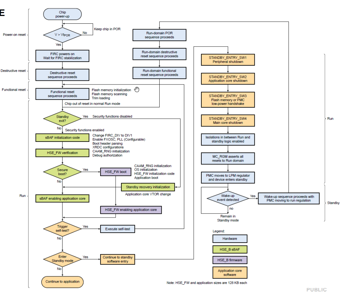
The items tagged red are corresponding with the HSE firmware and the secure boot.
The reset process of the chip is shown in the following diagram:
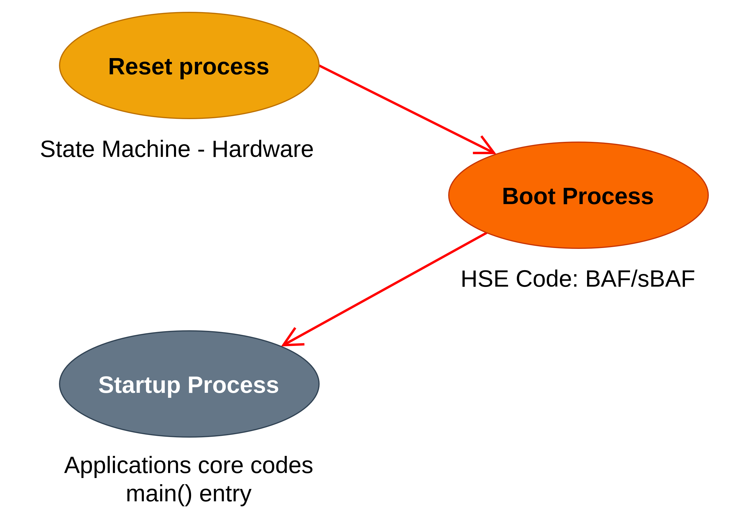
We can separate two boot stages at the point of the HSE core, which are respectively before and behind the HSE core, the Reset process and Startup Process:
- Stage I: Reset process (State machine - hardware): From any type of reset to before first instruction of HSE Core.
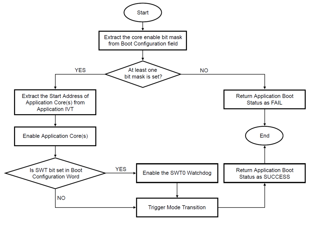
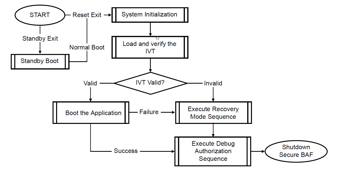
- Stage II: Boot process (HSE code: BAF/sBAF): From first HSE core instruction to before first instruction of Application Cores
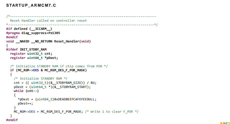
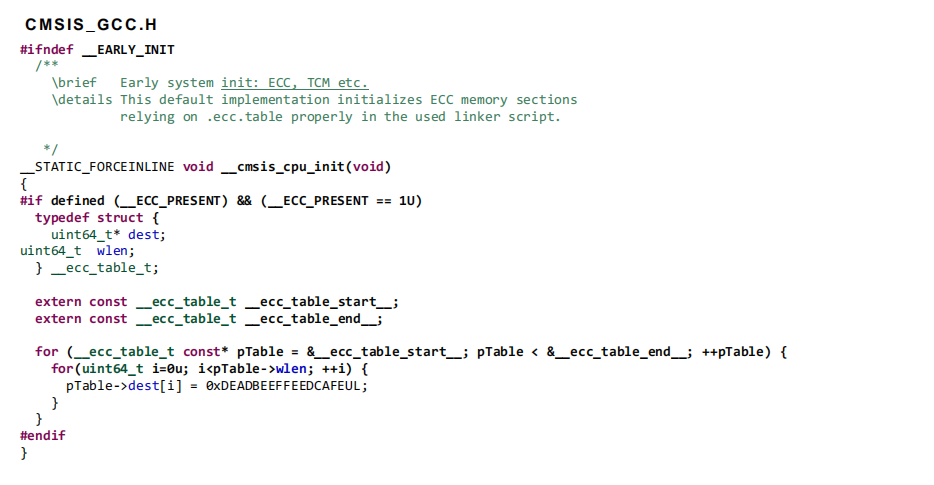
- Stage III: Startup process (Applications core codes) From first instruction of Application Cores to before first instruction on main ().
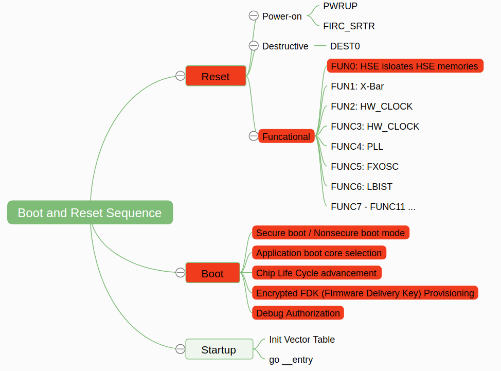
The following figure shows the all sub-stages of the boot and reset sequence:
- Reset Stage, the hardware and chip level initialization.
- Boot Stage, the firmware (such as HSE) level initialization.
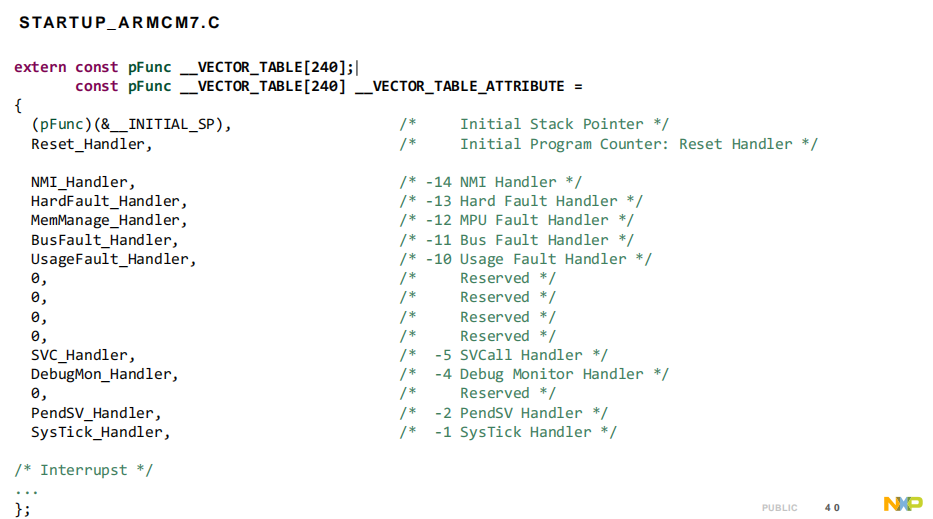
- Startup Stage: the user app entry and the interrupt vectors.
1. Reset Process
The blocks are shown in the following diagram:
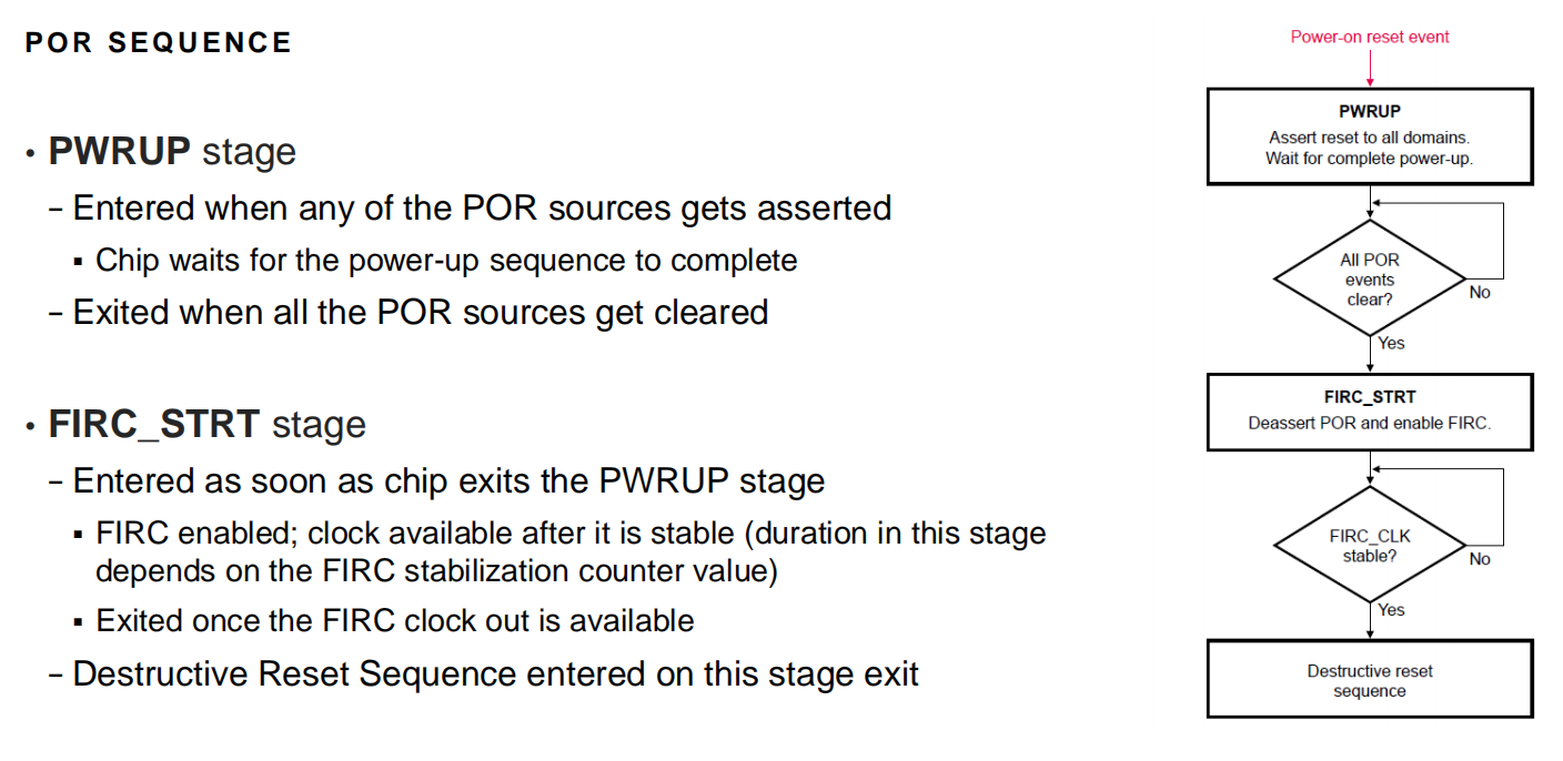
- Power-on reset
- The complete device gets reset when power is applied
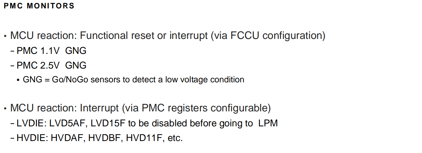
- All PMC (Power Management Controllers) POR and LVRs are combined into one single MCU POR.
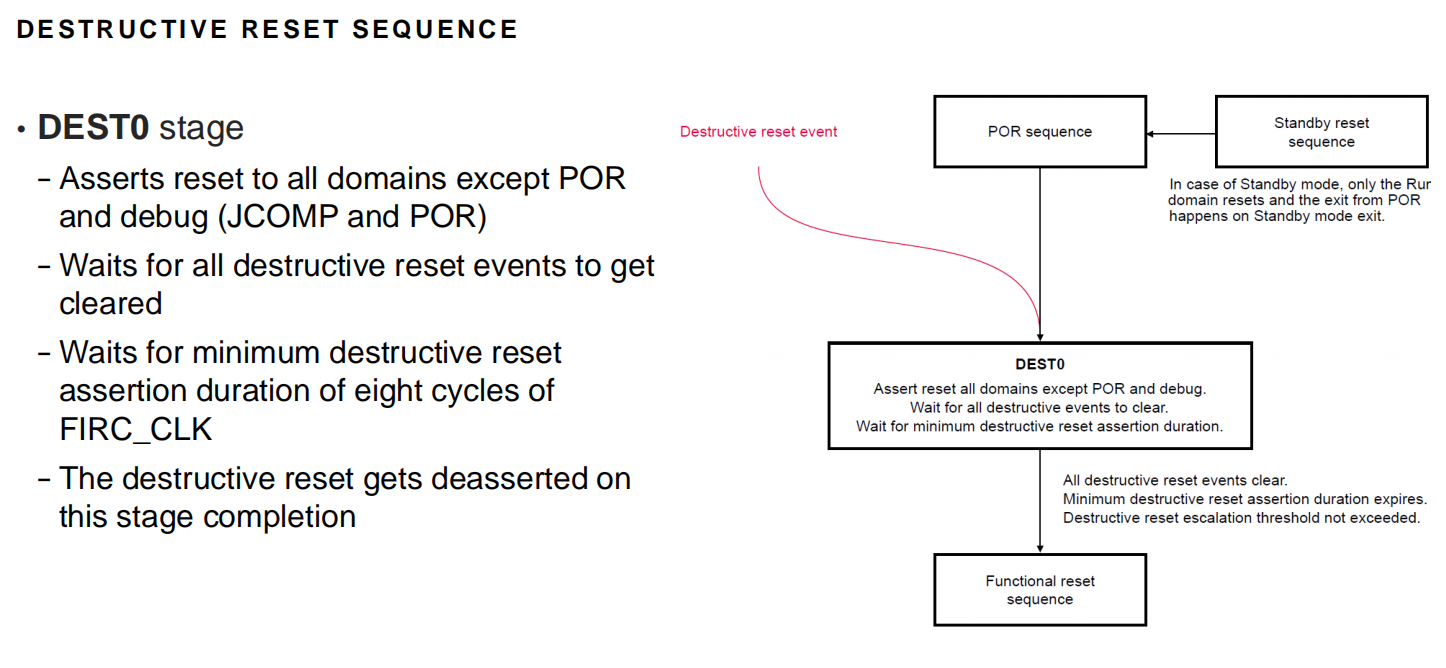
- Destructive reset
- associated with a critical error or dysfunction.
- full reset sequence applied, starting from DEST0, ensuring a safe start-up state for both digital and analog modules. The memory content must be considered to unknown state.
- Functional reset
- associated with a less-critical error or dysfunction
- partial reset sequence applied, starting from FUNCm0. Most digital modules are reset normally, while the state of analog modules or specific digital modules (for example, debug modules, flash modules) as well as the system memory content is preserved.
1.1 Power on Reset
1.2 Destructive Reset
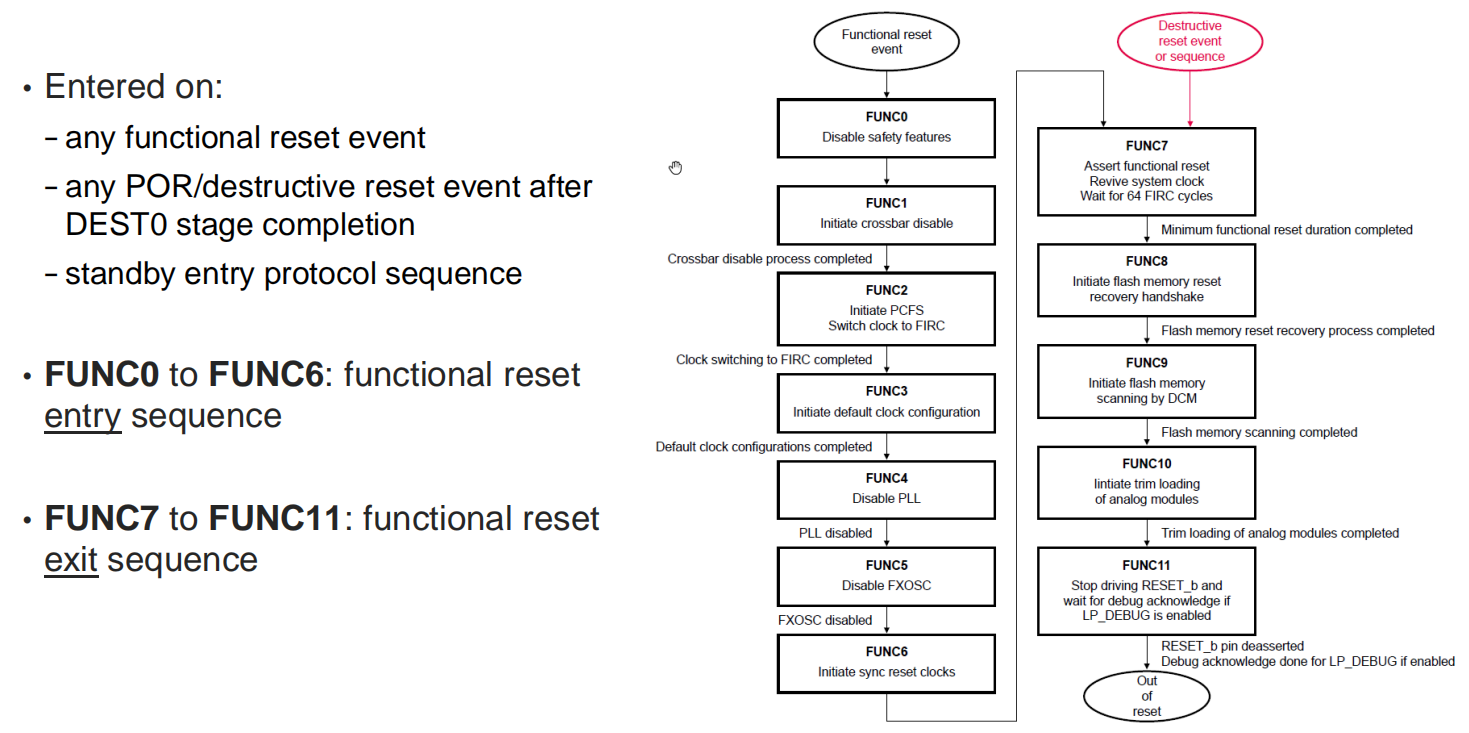
1.3 Functional Reset
- FUNC0: HSE isolates the HSE memories. FCCU fault monitoring and CMU monitoring for FLL events is masked
- FUNC1: X-bar disabled
- FUNC2: MC_CGM HW-clock multiplexers switch to FIRC clock
- FUNC3: MC_CGM HW-clock multiplexer dividers use their default values
- FUNC4: PLL is switched off in synchronous manner
- FUNC5: FXOSC is switched off in synchronous manner
- FUNC6: Clocks of LBIST modules, and modules working on destructive reset are enabled to meet synchronous reset requirement
- FUNC7: Functional reset asserted, a 64 FIRC clock counter is triggered, to enable clocks for the modules having synchronous reset requirements
- Flash memory comes out of reset on completion of this stage
- FUNC8: Flash-MC_RGM handshake
- FUNC9: DCM initiates the scanning of flash DCF records
- The device configuration sheet is attached in the RM as S32K3xx_dcf_sheet.xlsx, and describes the device DCF records
- FUNC10: DCM initiates trim loading sequence for analog blocks
- FUNC11: RGM stops driving RESET_B and checks if RESET_B is not asserted externally. If low power debug is enabled, MC_RGM waits for debug acknowledgement.
2. Boot Process
- Secure and nonsecure boot modes
- Application boot core selection
- Chip LC (Life Cycle) advancement
- Encrypted FDK (Firmware Delivery Key) provisioning
- Debug authorization
Note, BAF is the Secure Boot Assist Flash.
The IVT shall be:
3. Startup Process
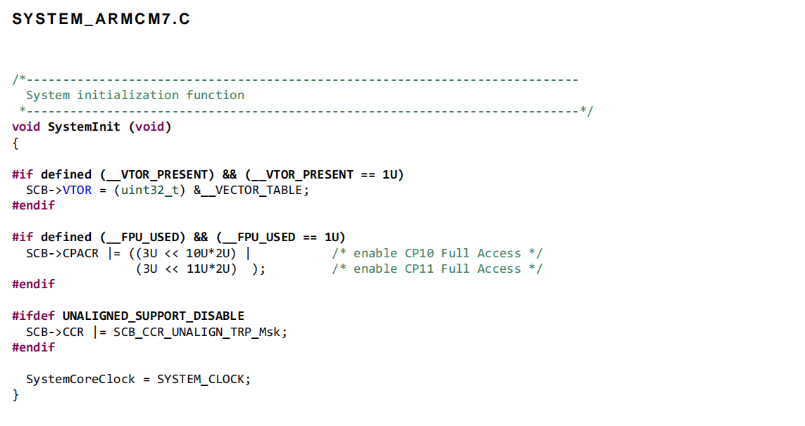
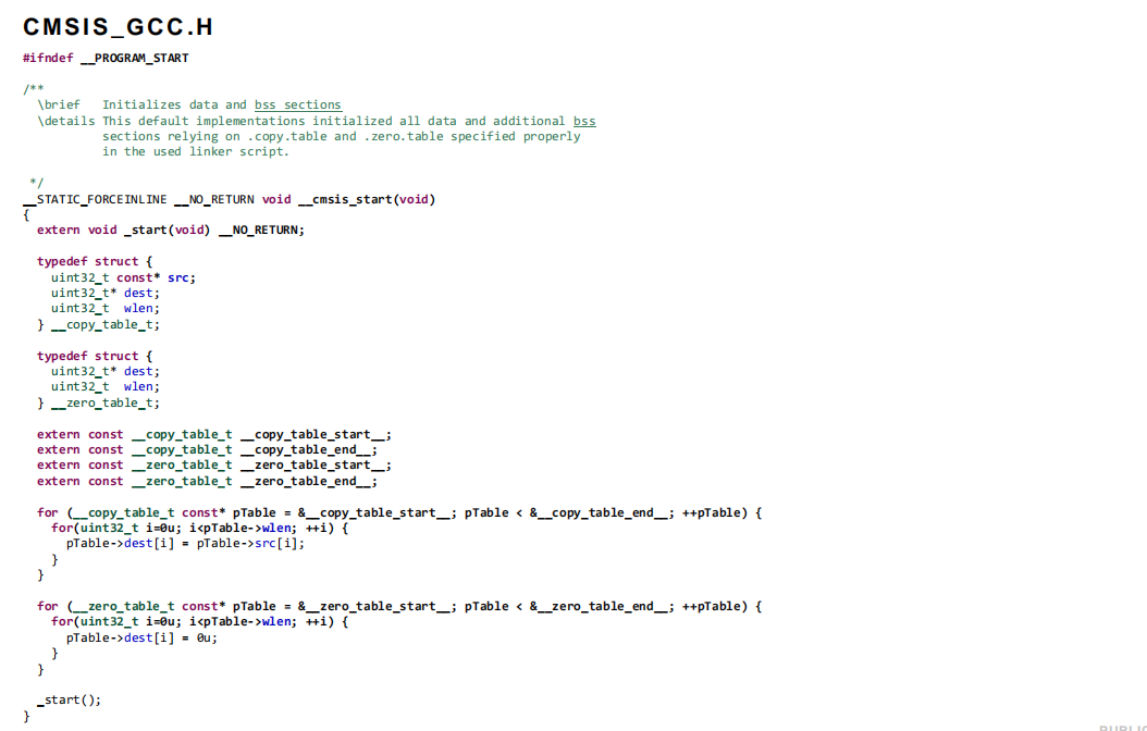
Startup process (Applications core codes) From first instruction of Application Cores to before first instruction on main ().
APPLICATION BOOT SEQUENCE:

![IVT (IMAGE VECTOR TABLE) HEADER STRUCTURE [ BOOT_HEADER.C ]](https://raw.githubusercontent.com/carloscn/images/main/typora202406250911687.png)
