Fast SPI library for the GC9A01A IPS display optimized for AVR Arduinos
Significantly optimized for 16MHz AVR Arduino boards (2.5-5x faster than other libraries).
Achieved 7.1Mbps SPI transfer rate (at DIV2/16MHz clock).
In compatiliblity mode it should work with other MCUs, but I didn't test all configurations.
YouTube video:
YouTube playlist with all videos related to fast Arduino IPS library:
https://www.youtube.com/playlist?list=PLxb1losWErZ7thUyB05phRR3DoiYN_kcD
Use #define COMPATIBILITY_MODE - then the library should work on all Arduino compatible boards
Remove above for the best performance on 16MHz AVR
Use #define CS_ALWAYS_LOW for LCD boards where CS pin is internally connected to the ground, it gives better performance
Optimized fast line clipping (#define FASTLINE_CLIP mode): #0=off, #1=cut corners, #2=clip using circle
Use "#define FASTLINE_CLIP 2" for maximum performance
I you need fullscreen scrolling use rather regular clipping "#define FASTLINE_CLIP 0"
Tested with Arduino IDE 1.6.5 and Adafruit_GFX 1.5.6
- invertDisplay()
- sleepDisplay()
- enableDisplay()
- idleDisplay() - saves power by limiting colors to 3 bit mode (8 colors)
- resetDisplay() - software reset
- partialDisplay() and setPartArea() - limiting display area for power saving
- setScrollArea() and setScroll() - smooth vertical scrolling
- fast drawImage() from RAM
- fast drawImage() from flash (PROGMEM)
- optimized fast line clipping #0=off, #1=cut corners, #2=clip using circle, use "#define FASTLINE_CLIP mode"
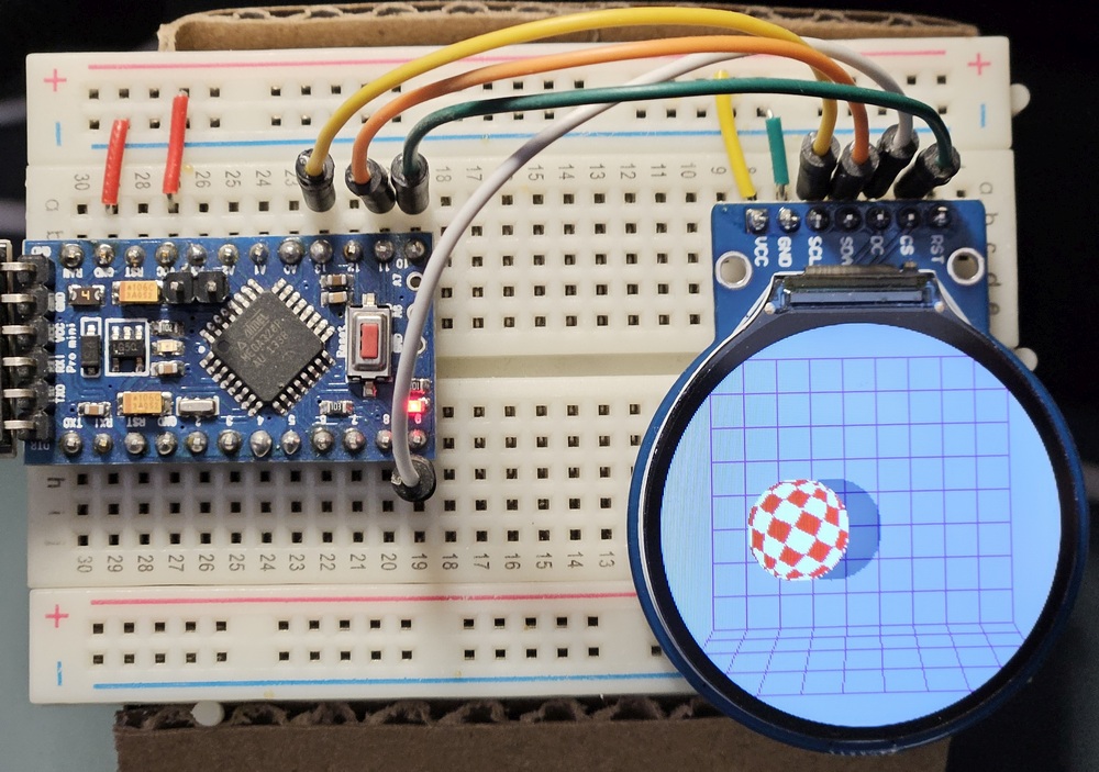
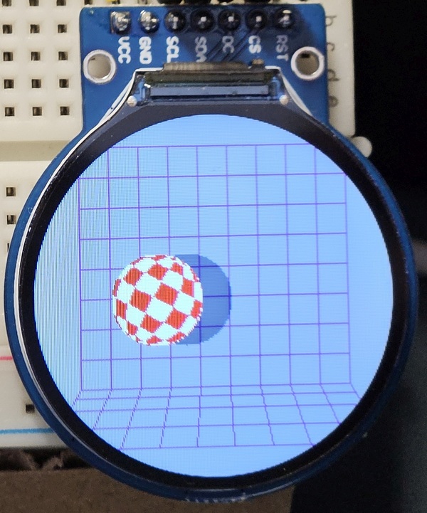
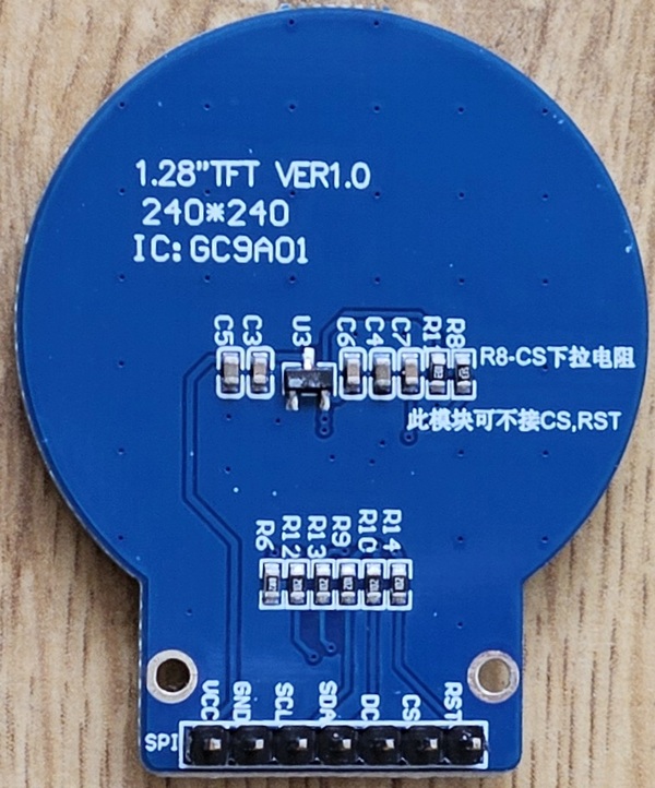
- round 240x240 1.28" IPS on round PCB
| Circuit | Front | Back |
|---|---|---|
 |
 |
 |
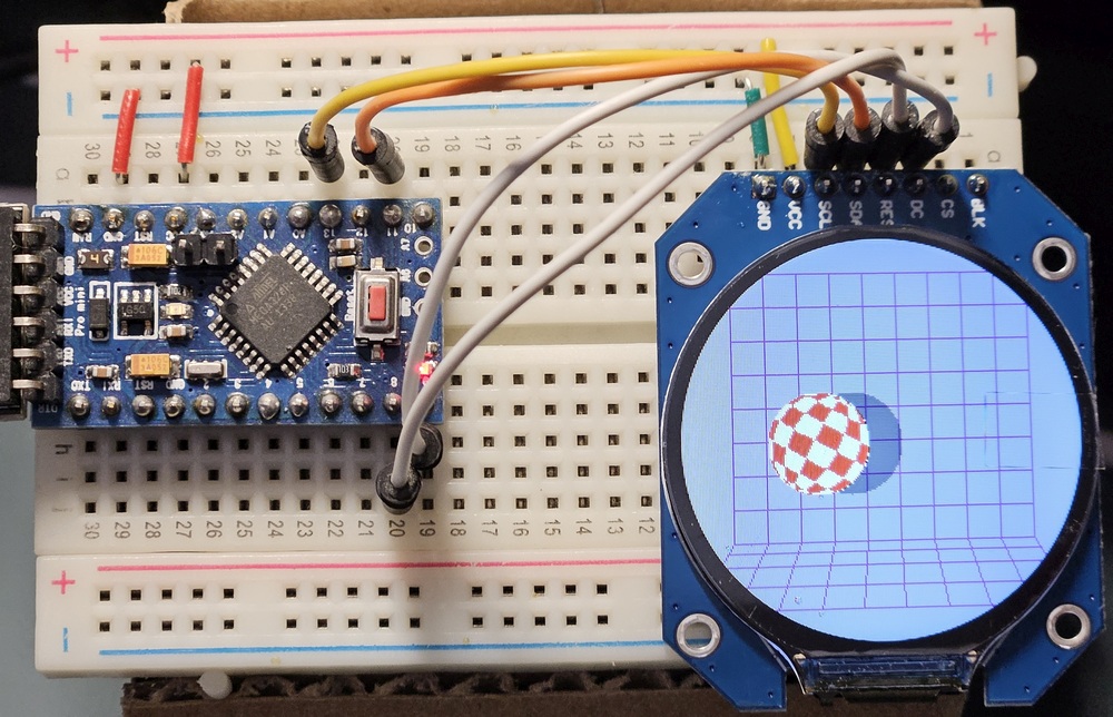
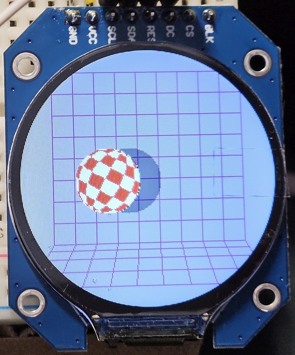
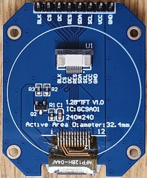
- round 240x240 1.28" IPS on square PCB
| Circuit | Front | Back |
|---|---|---|
 |
 |
 |
Variant with round PCB and RST+DC only, default setRotation(2)
| LCD pin | LCD pin name | Arduino |
|---|---|---|
| #01 | VCC | VCC (3.3V only?) |
| #02 | GND | GND |
| #03 | SCL | D13/SCK |
| #04 | SDA | D11/MOSI |
| #05 | DC | D9 or any digital |
| #06 | CS | optional, when not used then CS_ALWAYS_LOW should be defined |
| #07 | RST | D10 or any digital |
Variant with round PCB and CS+DC only
| LCD pin | LCD pin name | Arduino |
|---|---|---|
| #01 | VCC | VCC (3.3V only?) |
| #02 | GND | GND |
| #03 | SCL | D13/SCK |
| #04 | SDA | D11/MOSI |
| #05 | DC | D9 or any digital |
| #06 | CS | D10 or any digital |
| #07 | RST | NC |
Variant with square PCB and RST+DC only, use setRotation(0)
| LCD pin | LCD pin name | Arduino |
|---|---|---|
| #01 | GND | GND |
| #02 | VCC | VCC (3.3V only?) |
| #03 | SCL | D13/SCK |
| #04 | SDA | D11/MOSI |
| #05 | RST | D10 or any digital |
| #06 | DC | D9 or any digital |
| #07 | CS | optional, when not used then CS_ALWAYS_LOW should be defined |
| #08 | BLK | NC or VCC |
If you find it useful and want to buy me a coffee or a beer:


