This project has instructions and code for wiring up an INA219 current and voltage sensing chip with an XBee3 with MicroPython and filesystem support.
Specifically this project uses a Digi XBee Cellular LTE Cat 1 Verizon development kit (XKC-V1T-U) with an Adafruit INA219 FeatherWing.
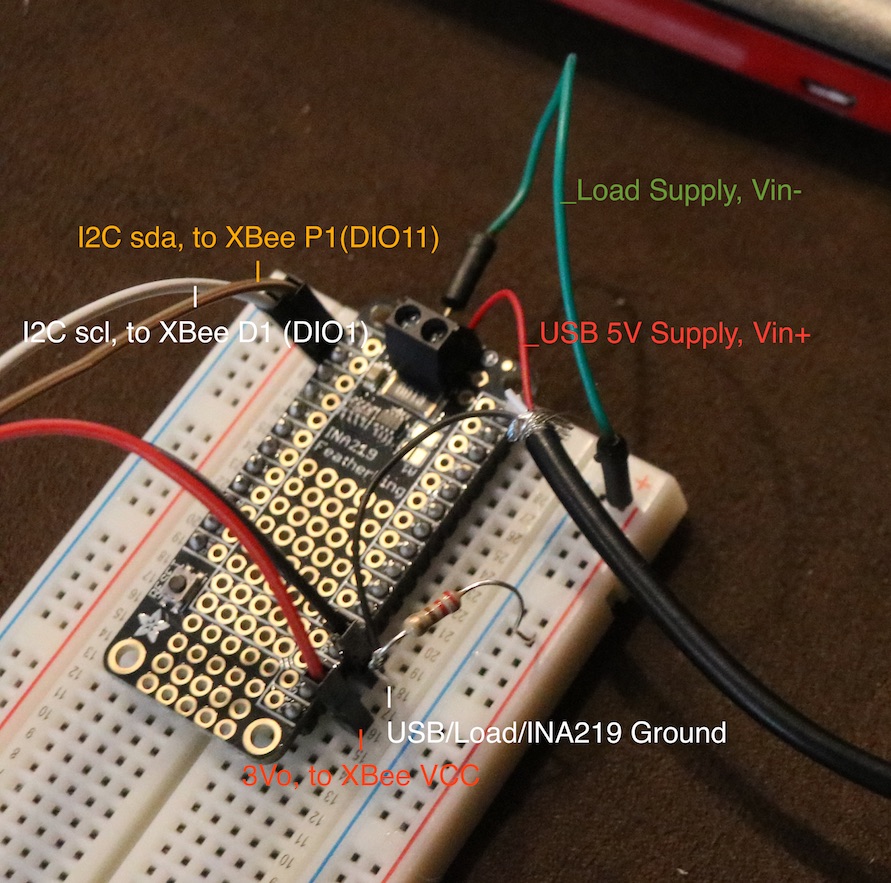
- Connect the 3Vo pin of the FeatherWing to the VCC pin of the XBee Cellular dev board
- Connect the GND pin of the FeatherWing to the GND pin of the XBee Cellular dev board
- Connect the scl pin of the FeatherWing to the D1 (DIO1) pin of the XBee Cellular dev board
- Connect the sda pin of the FeatherWing to the P1 (DIO11/PWM1) pin of the XBee Cellular dev board

Make sure you're running a version of firmware tha supports a filesystem for your XBee device. If this is the first time upgrading to firmware supporting a filesystem you may need to format it with:
ATFS FORMAT confirm
Download the following files. We'll use them for interacting with the INA219.
https://raw.githubusercontent.com/micropython/micropython-lib/master/logging/logging.py https://raw.githubusercontent.com/chrisb2/pyb_ina219/master/ina219.py
To reduce memory use we'll cross compile the dependencies so we can upload the compiled variants rather than the source files that can take more than the available memory to compile.
You can use pip to install the cross compiling tools
pip install mpy-cross
and then cross compile the dependencies with the following flags to ensure the compiled files are compatible
python -m mpy_cross -mno-unicode -msmall-int-bits=31 logging.py
python -m mpy_cross -mno-unicode -msmall-int-bits=31 ina219.py
Upload logging.mpy and ina219.mpy to your device.
Go ahead and upload math.py at this time as well. You can cross compile it if you want, but it's a very tiny module that just includes the trunc method which ina219.py uses. If your device happens to support the math module natively you can skip this step.
Running our code. The code in xbee_ina219.py sets up the XBee Cellular i2c device and passes it to the INA219 library and then prints out a power reading.
To run this code you can use the flash compile mode on the XBee. Copy the code in xbee_ina219.py and then hit Ctrl-F in a MicroPython interpreter terminal. Paste the code and hit Ctrl-D. Enter N to skip running the code automatically. You can now hit Ctrl-R to run the code and get a power reading.
At this point you are ready to hook up a load to measure.
- The positive voltage of your supply should go to the Vin+ of the INA219 board
- The Vin- of the INA219 breakout should go to the supply side of the load
- The ground side of your load should go to the ground of your supply as normal
- The ground side of your load should also go to the ground of the INA219 breakout for voltage measurement
I used a USB power supply and tested a 220 ohm resistor as my load wired up as shown in this image:
with the the following output after running the code in xbee_ina219.py:
Running 388 bytes of stored bytecode...
Bus Voltage: 5.208 V
Current: 23.805 mA
Power: 123.902 mW
We can calculate the expected power dissipation of a resistor with V^2/R, so (5.208^2)/220 = 123.29 mW shows we have a very reasonable measured power and current.
XBee Cellular User Guide: https://www.digi.com/resources/documentation/digidocs/90001525 Digi MicroPython Programming Guide: https://www.digi.com/resources/documentation/digidocs/90002219 Adafruit INA219 Tutorial: https://learn.adafruit.com/adafruit-ina219-current-sensor-breakout INA219 MicroPython Library README: https://github.com/chrisb2/pyb_ina219