This design is purely based on Texas Instruments Single-Supply, Electret Microphone Pre-Amplifier Reference Design by John Caldwell
The Jupyter notebook is basically a interactive Version of that reference design PDF. I claim no copyright on this.
The included Jupyter Notebook is an interactive version of the reference design PDF from Texas instruments. You can play with all values and let the program re-calculate all relevant values to be used in your own design.
There are some areas that will be most important:
- Operating Voltage of the Preamp
- Parameters of the Microphone capsule in use
- Acceptable high-frequency attenuation
- Acceptable low-frequency cutoff in output highpass filter
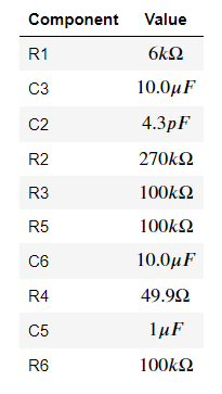
- The List of passive component values
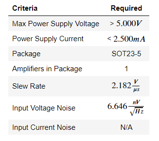
- The Op-Amp parameters to look out for
I have simulated the circuit in LTSpice with some different Op-Amps I had in stock.
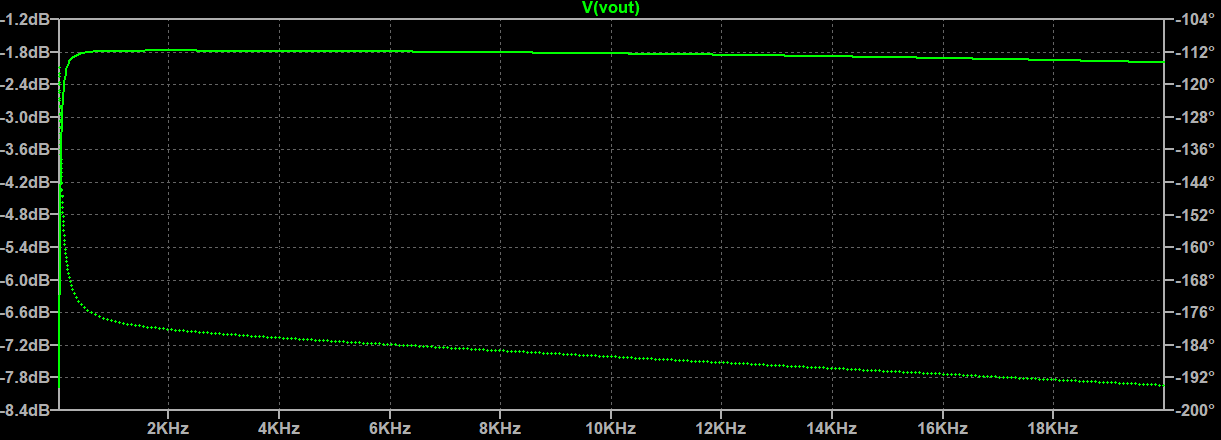
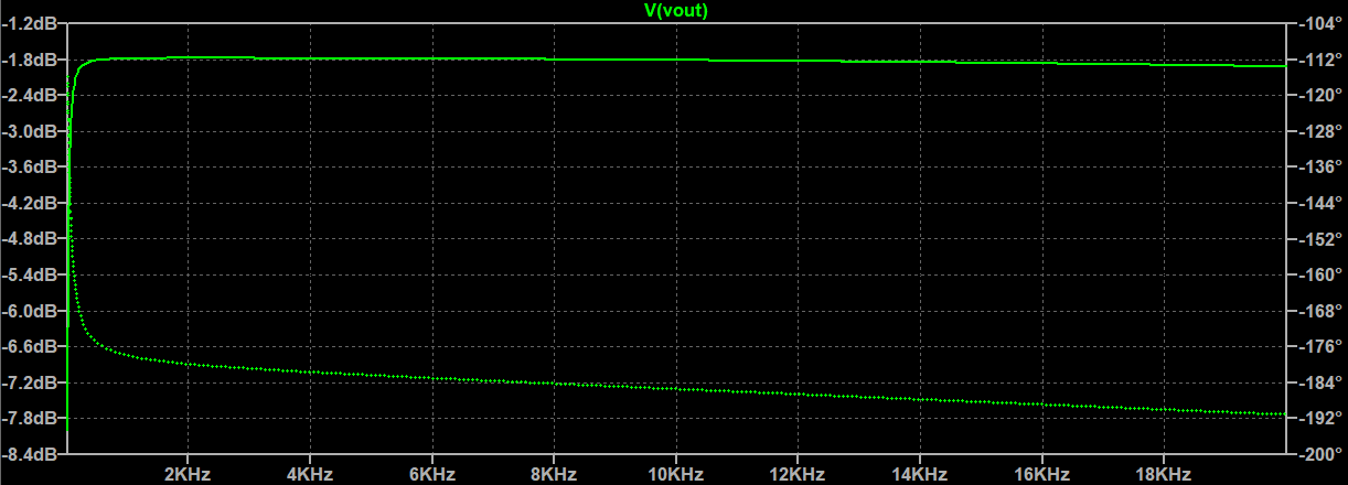
I deviated from the 270k resistor in the Op-Amp feedback loop and opted for a 180k value. This
means the amplification of the Op-Amp will not reach 0dB (max. seems to be around -1.8dB) but the circuit seems
to run more stable at that amplification.
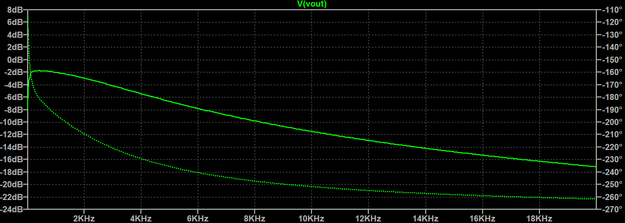
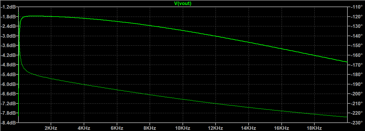
Here are some bode-plots of the frequency response for some tested Op-Amps:
The OP07 is the worst possible of the bunch. The bad response is a product of the sub-optimal slew rate of .
Additionally this Op-Amp will add noise to the signal as it's input voltage noise is around
. Ideally
it should be below
as we can see in the calulations.
The TL072 is a bit better than the OP07. The slew rate of is at least enough.
This Op-Amp will add a lot of noise to the signal as it's input voltage noise is around
. Ideally
it should be below
as we can see in the calulations.
The NE5532 is really good at this. All parameters are within the parameter range we calculated.
You can see why the LM318 is used for these applications a lot, as it is a dedicated Audio-Op-Amp the response from this thing is the best of the bunch.
Attention: The LM318 needed 5.3V operating voltage to actually do anything in the simulation, I have not
verified if this is an artifact of the simulation or an actual problem!
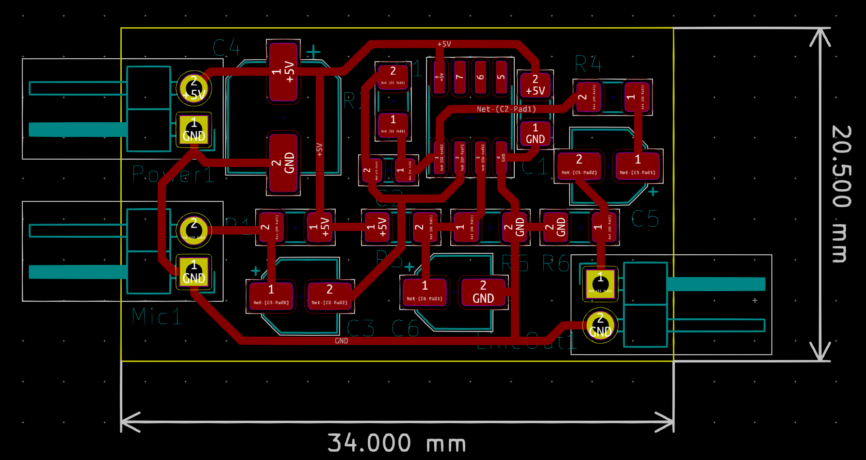
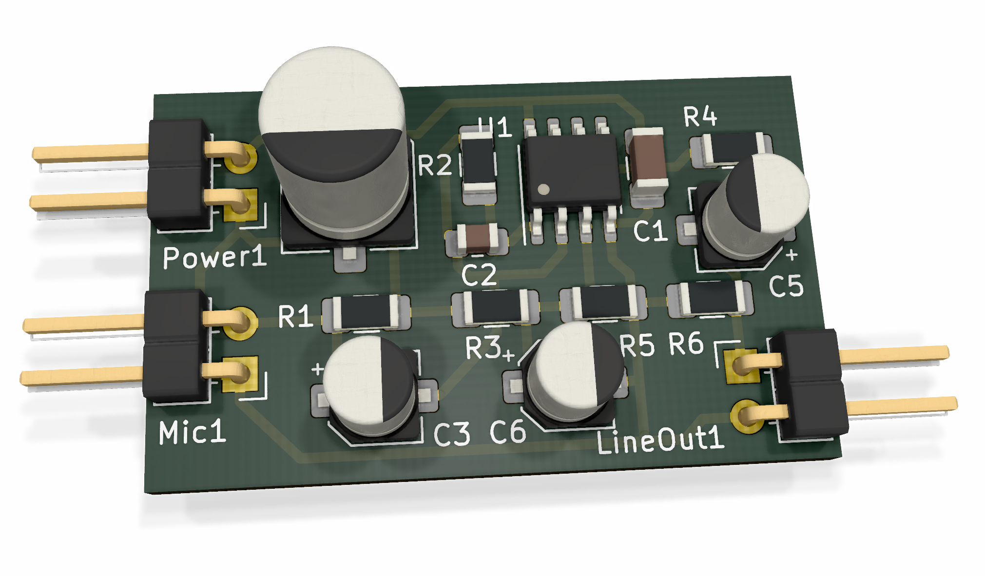
The KiCAD design is based on surface mount components to save as much space as possible. You could use tantalum capacitors instead of the electrolyte I used here, but they are expensive and I don't have them in stock.
The board design is optimized for space and to be single sided as it is easier to prototype this way. I will probably add a better two sided design in the future which will be optimized for noise performance and will probably get even smaller (but I have to order the PCBs then)
This is what the board looks like rendered, I will add a photo of the finished product when I have built one.


