This repository is a Python package to help teach and learn the math of 3D rotation. It has two modules:
- pyrotation_demo.py - contains GUI based interactive demo of 3D rotation of reference frame.
- pyrotation.py - contains the core class and routines for representation and operation of 3D rotation.
Both modules are tested on Python 3.6, NumPy 1.19, Matplotlib 3.1.2.
See the slides to learn the representations of 3D rotation.
The pyrotation_demo module provides four interactive GUI visualizers based on the matplotlib, corresponding to the four representations of the 3D rotation implemented in the pyrotation module. Users can drag sliders to directly change parameters of the representation and the corresponding rotation of reference frame is shown in real-time. This demo is mainly made for learning how 3D rotation work.
This module requires numpy, matplotlib, and the pyrotation module.
The pyrotation module provides four different representations of a 3D rotation as well as corresponding operations on these representations:
- Angle-axis - represented as a numpy 3-dimensional vector u, where its direction is the axis and its length is the angle (the angle could be negative, which means the rotation uses the opposite direction of the vector). The rotation follows the right-hand rule.
- Euler angles (in z-y'-x" intrinsic convention) - represented as a tuple of three angles (z, y, x). These angles are also called Tait-Bryan angles, or (yaw, pitch, roll) angles. There are other conventions of Euler angles and only this specific notation is implemented and used in the demo.
- Rotation matrix - represented as a numpy 3-by-3 matrix R.
- Unit quaternion - represented as an object q of a custom quaternion class defined in the pyrotation module. The quaternion is in Hamiltonian convetion, i.e., (qw, qx, qy, qz).
This module requires numpy. In all cases, coordinate of a 3D point is represented as a numpy 3-dimensional vector. Array of 3D points is represented as numpy 3-by-n matrix, where n is the number of points. The coordinate reference frame is right-handed.
Just download pyrotation.py and pyrotation_demo.py, and run.
Put both pyrotation.py and pyrotation_demo.py into the same folder, and launch the demo using the following command.
$ python3 ./pyrotation_demo.py [mode]
The "mode" can be one of the following:
- "u" or "angle_axis" - angle-axis (default if mode is not given)
- "e" or "euler" - Euler angles (in z-y'-x" intrinsic convention)
- "r" or "R" or "rotation_matrix" - rotation matrix
- "q" or "quaternion" - unit quaternion
For example, if the following command is used,
$ python3 ./pyrotation_demo.py q
Then the demo with quaternion is shown.
Common explanations:
-
In all demoes, the axes uses this color settings.
- the x-axis is red.
- the y-axis is green.
- the z-axis is blue.
-
The three axes of the original reference frame are represented in dashed lines with black and color alternation, and the rotated reference frame are represented in solid lines with colors.
-
A solid disk on the XOY plane in the original reference frame is shown to represent the "ground"
Explanations:
-
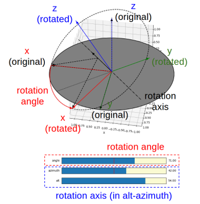
In the demo GUI, the rotation axis is represented in a dotted and dashed line through the origin. The rotation vector, i.e., the vector u, is shown as a solid black arrow on the axis. The projection of the axis on the ground is shown as a dotted line.
-
Besides, a dashed circle is shown, where the rotation axis is through the center of the circle and perpendicular to the plane of the circle. Two dashed arrows are on this plane pointing from the center of the circle to the original and rotated x-axis. On the circle, a red arc with arrow shows the rotation angle, pointing from the original x-axis to the rotated x-axis. Together they show the conic shape of rotating a vector or point along an axis.
-
Note that this axis is always throught the origin. An arbitrary rotation with an axis not going through the origin can be decomposed into a translation from a point on the axis to the origin, a rotation with an axis through the origin, and another translation back to the point.
-
The rotation angle and the rotation axis can be directly controlled by the three sliders. Note that to control the axis, alt-azimuth angles of the axis are used. Thus, even in the degenerated case, where the rotation angle is zero, the axis can still be defined using the alt-azimuth angles (the dotted line representing the projection of the axis on the ground is calculated by the azimuth angle, so even the axis is pointing to perpendicular to the ground, this dotted line is still defined and shown). The rotation angle is in
[-180, +180]degrees, the alt angle is in[-90, +90]degrees, and the azimuth angle is in[-180, +180]degrees.
Explanations:
-
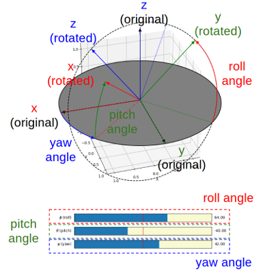
Yaw angle is shown as a blue arc on the ground, pointing from the x-axis of the original frame to the projection of the rotated x-axis on the ground.
-
Pitch angle is shown as a green arc, pointing from where the yaw angle arc ends to the rotated x-axis, i.e., from the tip of the projection of the rotated x-axis on the ground, which is shown as a dotted red line, to the tip of the rotated x-axis.
-
Roll angle is shown as a red arc in the rotated YOZ plane on a dashed circle, pointing from the tip of the projection of the rotated y-axis on the ground, which is shown as a dotted green line, to the tip of the rotated y-axis.
-
The projection of the z-axis of the original reference frame on the YOZ plane of the rotated reference frame is shown as a dotted blue line.
-
The three Euler angles can be directly controlled by the three sliders. All three angles are in
[-180, +180]degrees. Even in the gimbal lock case, where the pitch angle is -90 degree or +90 degree, the yaw angle and the roll angle can be independently controlled, though their effects would be indistinguishable in this case.
Explanations:
-
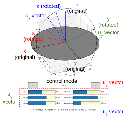
To construct a rotation matrix, three orthonormal basis vectors of the rotated reference frame are needed. However, since these three basis vectors are orthonormal, once two vectors are given (or one plane and a vector on the plane are given), the three basis vectors and the rotation matrix can be uniquely determined. This demo provides three modes as follows, and the current mode can be changed using the two buttons with "<-" and "->" arrows.
-
"ux-uy", where the "ux" vector is the x-axis of the rotated reference frame, and "ux" and "uy" vectors together defines the XOY plane of the rotated reference frame. This plane is shown as a dashed circle. In this mode, "ux" is shown as a solid red line (i.e., the x-axis after rotation), and "uy" is shown as a dashed green line.
-
"uy-uz", where "uy" vector is the y-axis of the rotated reference frame, and "uy" and "uz" vectors together defines the YOZ plane of the rotated reference frame. This plane is shown as a dashed circle. In this mode, "uy" is shown as a solid green line (i.e., the y-axis after rotation), and "uz" is shown as a dashed blue line.
-
"uz-ux", where "uz" vector is the z-axis of the rotated reference frame, and "uz" and "ux" vectors together defines the ZOX plane of the rotated reference frame. This plane is shown as a dashed circle. In this mode, "uz" is shown as a solid blue line (i.e., the z-axis after rotation), and "ux" is shown as a dashed red line.
-
-
The three basis vectors of the rotated reference frame can be directly controlled using the sliders. Since they are all unit vectors (i.e., only the directions are important and their length do not matter), this demo program uses alt-azimuth angles to control them. In each mode, two vectors can be controlled and changing the third vector has no effect.
-
The projection of the two control vectors on the ground are shown as dotted lines with their corresponding colors. They are derived from the azimuth angles. The alt angles are in
[-90, +90]degrees, and the azimuth angles are in[-180, +180]degrees.
Explanations:
-
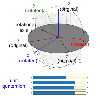
The rotation angle-axis, i.e., the vector u, corresponding to the unit quaternion is shown as a solid black arrow. The YOZ plane of the rotated reference frame is shown as a dashed circle.
-
The four components of the unit quaternion can be directly controlled by the four sliders. However, it is not straightforward to manuplate a quaternion to a rotation that the user desires. Since it is a unit quaternion, the four components are coupled and the user can not change one component without influence to others. This demo program provides three ways as follows.
-
Changing the rotation angle while maintaining the axis, using the slider of qw. In this case, the other three components of the quaternion will be updated porpotionally to keep the direction of the rotation axis.
-
Changing the axis direction while maintaining the angle (always to pi), by changing one of qx, qy, and qz. In this case, qw is always set to 0, while the the other two components not directly changed using the sliders are nonzero and updated propotionally. This allows the rotation axis, the axis changed by the sliders, as well as the corresponding axis of the original reference frame always stay in the same plane. For example, if the slider of qx is changed while qy and qz are nonzero, the rotation axis, the original x-axis, and the x-axis after rotation are in the same plane. The other two axes also keep this same coplaner property when the rotation axis is changed.
-
Rotation along one of the axes of the original reference frame, by changing one of qx, qy, and qz. In this case, qw is always set to 0, while the other two components are also zero.
-
First, import the pyrotation module.
>>> import pyrotation
For angle-axis, Euler angles, and rotation matrix, they use just built-in Python types and Numpy types, i.e., no custom class are defined. Hence, a set of function operating on built-in and numpy types are provided. For quaternion, a custome Quaternion class is defined and all operations on a quaternion are methods of the class or object.
This module defines a value EPSILON, which is considered as the precision required for floating point comparison (typically 1e-6). For example, if the absolute value of a floating point number a is less than EPSILON, a is considered as zero when handling singularity. In the following documentation, "if a is zero" generally means "if the absolute value of a is less than EPSILON" in the code.
-
Use the
alt_azimuth_to_axis(alt_degree, azimuth_degree) -> ufunction to create a unit vectorurepresenting an axis from alt-azimuth angles in degrees. Note that the alt-azimuth angles are not restricted to be within a range. However, typicallyalt_degreeshould be in[-90, +90]degrees andazimuth_degreeshould be in[-180, +180]degrees. -
Use the
axis_to_alt_azimuth(u) -> (alt_degree, azimuth_degree, gimbal_lock, degenerated)function to conver an axis vectoruto alt-azimuth angles in degrees. If the length ofuis zero, thedegeneratedflag is set toTrue,alt_degreeis set to +90 degrees, andazimuth_degreeis set to 0 degree. Ifuis nonzero but pointing to the z-axis or the opposite of the z-axis, thegimbal_lockflag is set toTrue,alt_degreeis set to +90 degrees, andazimuth_degreeis set to 0 degree. -
Use the
rotate_a_point_by_angle_axis(p, u) -> rpfunction to rotate a pointpby an angle-axis rotaionuand obtain the rotated pointrp. Bothpandrpare numpy 3-dimensional arrays. -
Use the
rotate_points_by_angle_axis(ps, u) - rpsfunction to rotate an array of pointspsby an angle-axix rotationuand obtain the rotated array of pointsrps. Bothpsandrpsare numpy 3-by-n matrix where n is the number of points. -
Use the
angle_axis_to_rotation_matrix(u) -> Rfunction to convert an angle-axisuto a rotation matrixR. If the length ofuis zero, the identity matrix is returned. -
Use the
rotation_matrix_to_angle_axis(R) -> ufunction to convert a rotation matrixRto an angle-axisu. IfRis the identity matrix,uis all zero, i.e., degenerated.
-
Use the
euler_zyx_to_rotation_matrix(z, y, x) -> Rfunction to convert the (yaw, pitch, roll) angles in radian to a rotation matrixR. The three angles are in this order: z-yaw, y-pitch, x-roll. -
Use the
rotation_matrix_to_euler_angles_zyx(R) -> (z, y, x, gimbal_lock)function to convert a rotation matrix to the (yaw, pitch, roll) angles. If the rotation matrix represents a rotation corresponding to a pitch angle of -pi/2 degree or +pi/2 radian, i.e.,R[2, 0]is +1 or -1, thegimbal_lockflag is set toTrue. In this case, roll angle is always set to 0.
-
Use the
rotate_a_point_by_rotation_matrix(R, p) -> rpfunction to rotate a pointpby a rotation matrixRand obtain the rotated pointrp. Bothpandrpare numpy 3-dimensional arrays. -
Use the
rotate_points_by_rotation_matrix(R, ps) -> rpsfunction to rotate an array of pointspsby a rotation matrixRand obtain the rotated array of pointsrps. Bothpsandrpsare numpy 3-by-n matrix where n is the number of points. -
Use the
normalize_rotation_matrix(R) -> Rnfunction to normalize a rotation matrixRto obtain a normalized matrixRn. This function uses SVD. -
Use the
rotation_matrix_from_orthonormal_basis(ux, uy, uz) -> Rfunction to construct a rotation matrixRfrom three orthonormal basis vectors(ux, uy, uz). -
Use the
orthonormal_basis_from_two_vectors(v1, v2, v1_default, v2_default) -> (u1, u2, u3)function to construct three orthonormal basis vectors(u1, u2, u3)from a pair of vector(v1, v2), whereu1is in the direction ofv1,u2is in the plane defined byv1andv2, andu3is orthogonal to the plane ofv1andv2. In the degenerated case 1, wherev1is all zero,v1_defaultis used instead. In the degenerated case 2, wherev2is all zero orv2is in the same direction asv1,v2_defaultis used instead. There three helper functions based this one.rotation_matrix_from_xy(x, y) -> R, i.e., constructing a rotation matrixRgiven two vectors representing the x-axis and the y-axis.rotation_matrix_from_yz(y, z) -> R, i.e., constructing a rotation matrixRgiven two vectors representing the y-axis and the z-axis.rotation_matrix_from_zx(z, x) -> R, i.e., constructing a rotation matrixRgiven two vectors representing the z-axis and the x-axis.
For these three helper functions, the first axis is always in the same direction of the first provided vector. If the second provided vector is not orthogonal to the vector, a vector on the plane defined by these two vectors that is orthogonal the first vector is constructed as the the second axis. The third axis is always perpendiculer to the plan defined by the two provided vectors. The reference frame is always right-handed.
A unit quaternion is represented by an object of the class Quaternion defined in this module. The quaternion object is immutable after construction. All operations will return a new quaternion object instead of changing itself.
Some useful object methods are shown as follows.
-
Use
q.norm() -> nto get the norm of the quaternionq. -
Use
q.conjugate() -> qcto get the conjugate of the quaternionq, i.e., ifqis (w, x, y, z),qcis (w, -x, -y, -z). -
Use
q.inverse() -> qito get the inverse of the quaternionq. -
Use
q.negate() -> qnto get the negate of the quaternionq, i.e., ifqis (w, x, y, z),qnis (-w, -x, -y, -z). -
Use
q1.multiply_quaternion(self, q2) -> q3to get the composition ofq1andq2asq3, i.e.,q3=q1*q2, where "*" is quaternion multiplication. Note thatq1*q2is generally not equal toq2*q1.
For the following methods, q must be a unit quaternion and this method does not check that. If q is not a unit quaternion the results would be wrong.
-
Use
q.rotate_a_point(p) -> rpto rotate a pointpby a unit quaternionqand obtain the rotated pointrp. Bothpandrpare numpy 3-dimensional arrays. -
Use
q.rotate_points(ps) -> rpsto rotate an array of pointspsby a unit quaternionqand obtain the rotated array of pointsrps. Bothpsandrpsare numpy 3-by-n matrix where n is the number of points. -
Use
q.to_angle_axis() -> uto convert a unit quaternionqto an angle-axisu. -
Use
q.to_rotation_matrix() -> Rto convert a unit quaternionqto a rotation matrixR.
Some useful class methods are shown as follows.
-
Use
Quaternion.identity() -> qito construct the identity unit quaternionqi, i.e., (1, 0, 0, 0). -
Use
Quaternion.construct_from_angle_axis(u) -> qto convert an angle-axisuto a unit quaternionq. In the degenerated case whereuis all zero, the identity quaternion is returned. -
Use
Quaternion.construct_from_rotation_matrix(R) -> qto convert a rotation matrixRto a unit quaternionq. -
Use
Quaternion.interpolate(q0, q1, t) -> qto obtain a spherical linear interpolation (SLERP) of two unit quaternionsq0andq1given a parametert. Iftis 0,q0is returned, and iftis 1,q1is returned. Iftis between 0 and 1, a unit quaternionqrepresenting a rotation continuously from the orientationq0to the orientationq1at the fractiontis returned.
More quaternion kinematics will be implemented in the future.


