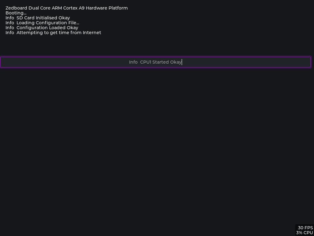
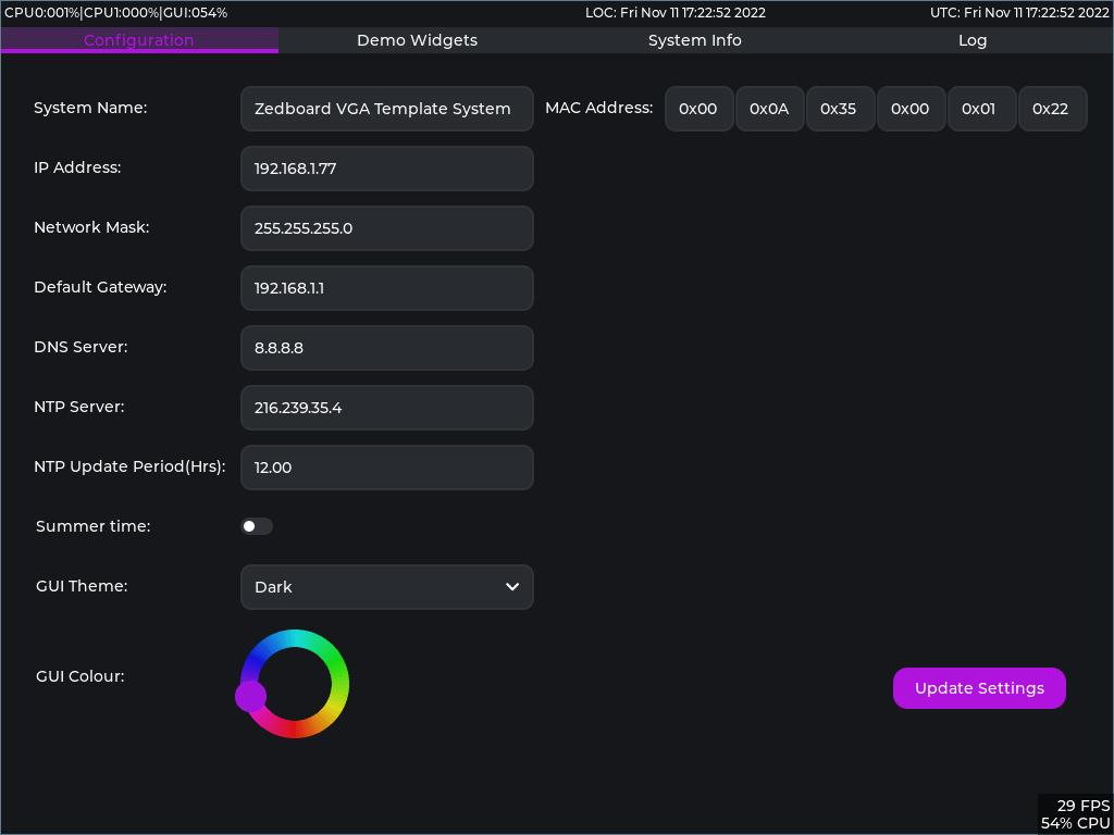
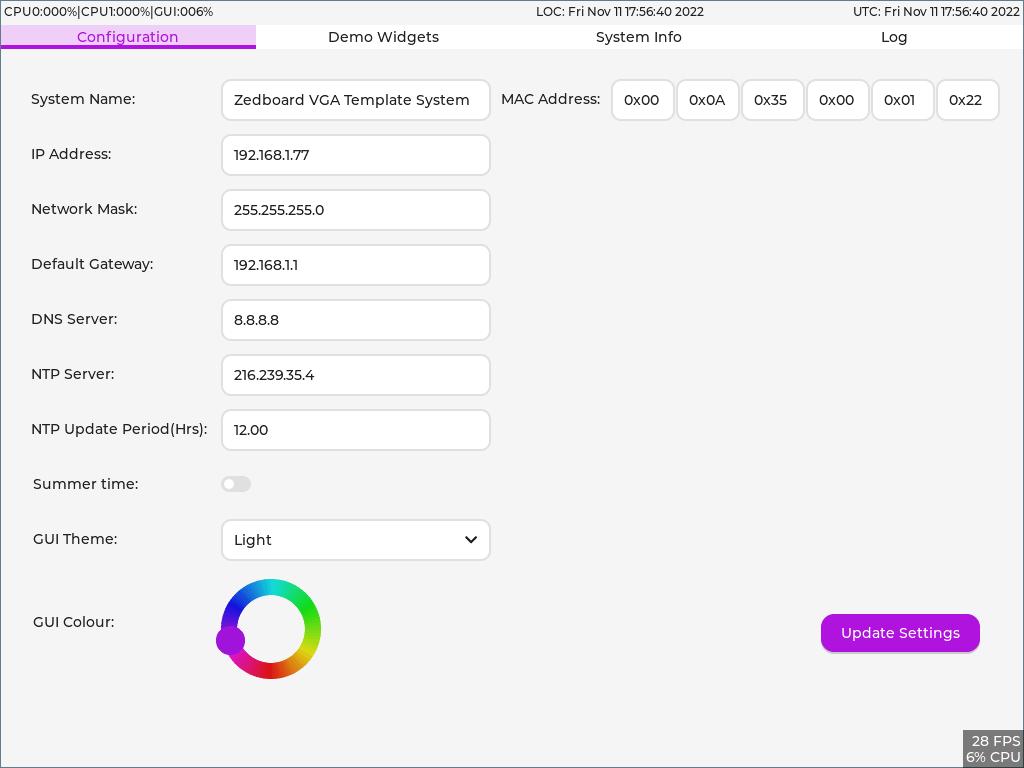
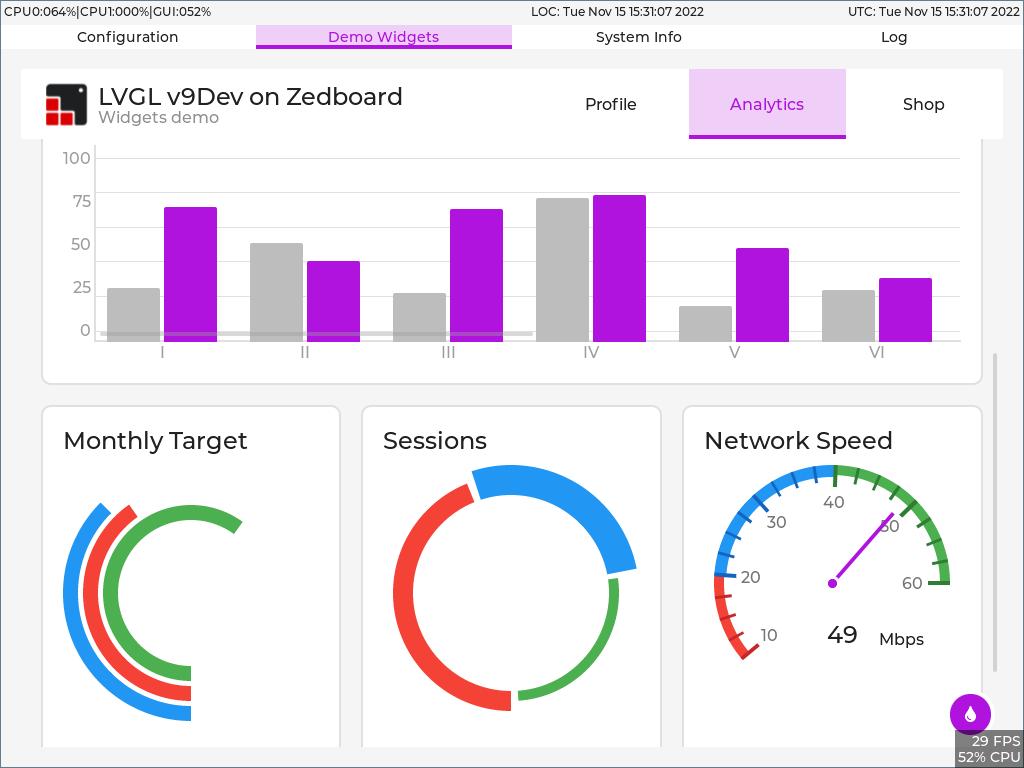
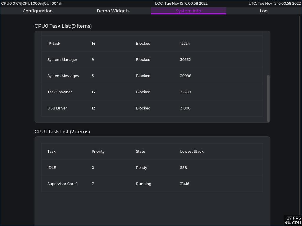
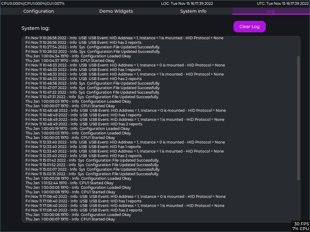
Being very grateful for the existence of open source projects such as FreeRTOS, LVGL and TinyUSB, this is an implementation of asymetrical multi-processing (AMP) FreeRTOS +TCP +FAT with LVGL graphics library driving a custom 'VGA IP' implemented in the FPGA fabric for the Zedboard. I just wanted to give something back to the community and hopefully this will prove a useful template for the Zedboard/Xilinx Zynq 7000 platform. See: https://digilent.com/shop/zedboard-zynq-7000-arm-fpga-soc-development-board/ and: https://www.xilinx.com/products/silicon-devices/soc/zynq-7000.html
FreeRTOS Kernel
https://github.com/FreeRTOS/FreeRTOS-Kernel.git
FreeRTOS-Plus-TCP
https://github.com/FreeRTOS/FreeRTOS-Plus-TCP.git
Lab-Project-FreeRTOS-FAT
https://github.com/FreeRTOS/Lab-Project-FreeRTOS-FAT.git
The light and versatile graphics library (LVGL)
https://github.com/lvgl/lvgl
Tiny USB
https://github.com/hathach/tinyusb
ARM Core 0 runs an instance of FreeRTOS implementing the FAT file system, the TCP/IP stack and the graphics library.
ARM Core 1 also runs an instance of FreeRTOS with just one task which drives the Zedboard OLED display.
Currently the home grown fabric VGA interface has worked successfully up to a resolution of 1440 x 900 @ 60 Hz. The configuration set for the example is 1024 x 768 @ 60 Hz. There are a number of standard resolutions defined in the code which can be used, but currently there is no dynamic selection, a resolution change requires a new firmware build. It wouldn't be difficult to add some code to change the display resolution at runtime and you could also create your own table entries for other resolutions. This site is a good source of VGA parameters: http://tinyvga.com/vga-timing
There is a very basic implementation of USB HID for keyboard, mouse and touch screen, which is heavily based on the Github TinyUSB project from @hathachX see here: https://github.com/hathach/tinyusb I have modified this code to work with the 'Zynq' in a non-cached way and created a couple of source files which contain the 'Zynq' specific implementation.
- A basic tab based GUI which enables configuration of the basics for a FreeRTOS +TCP/IP based system along with the primary colour of the GUI and the Dark/Light theme.
- An SD based file system using FreeRTOS +FAT on which a rudimentary log system has been implemented.
- A basic FTP server, enabling access to the file system to collect the log and configuration file, it also enables the update of the BOOT.BIN file on the system for firmware update.
- A basic NTP Client and Server application.
- I have implementated the LVGL widgets demo modified to run on a tab in the GUI also.
- There is a 'System Info' tab which shows the FreeRTOS tasks and stats.
Required Hardware:
Zedboard with SD card installed, a USB mouse can be used with a VGA compatable monitor connected to the Zedboard VGA connector, or a Touch screen connected to the VGA port and the USB port (See links below for Waveshare(Ilitek touch) screens I have used.)
https://www.waveshare.com/product/displays/lcd-oled/lcd-oled-1/13.3inch-hdmi-lcd-h-with-case.htm
https://www.waveshare.com/product/displays/lcd-oled/lcd-oled-1/15.6inch-hdmi-lcd-h-with-case.htm
NOTE: for Waveshare screens VGA connection, this cable is also required:
https://www.waveshare.com/Mini-HDMI-Male-to-VGA-Female-Cable.htm
You will very likely need a usb OTG adapter to adapt the microusb OTG socket to USB-A socket for a mouse or touch screen.
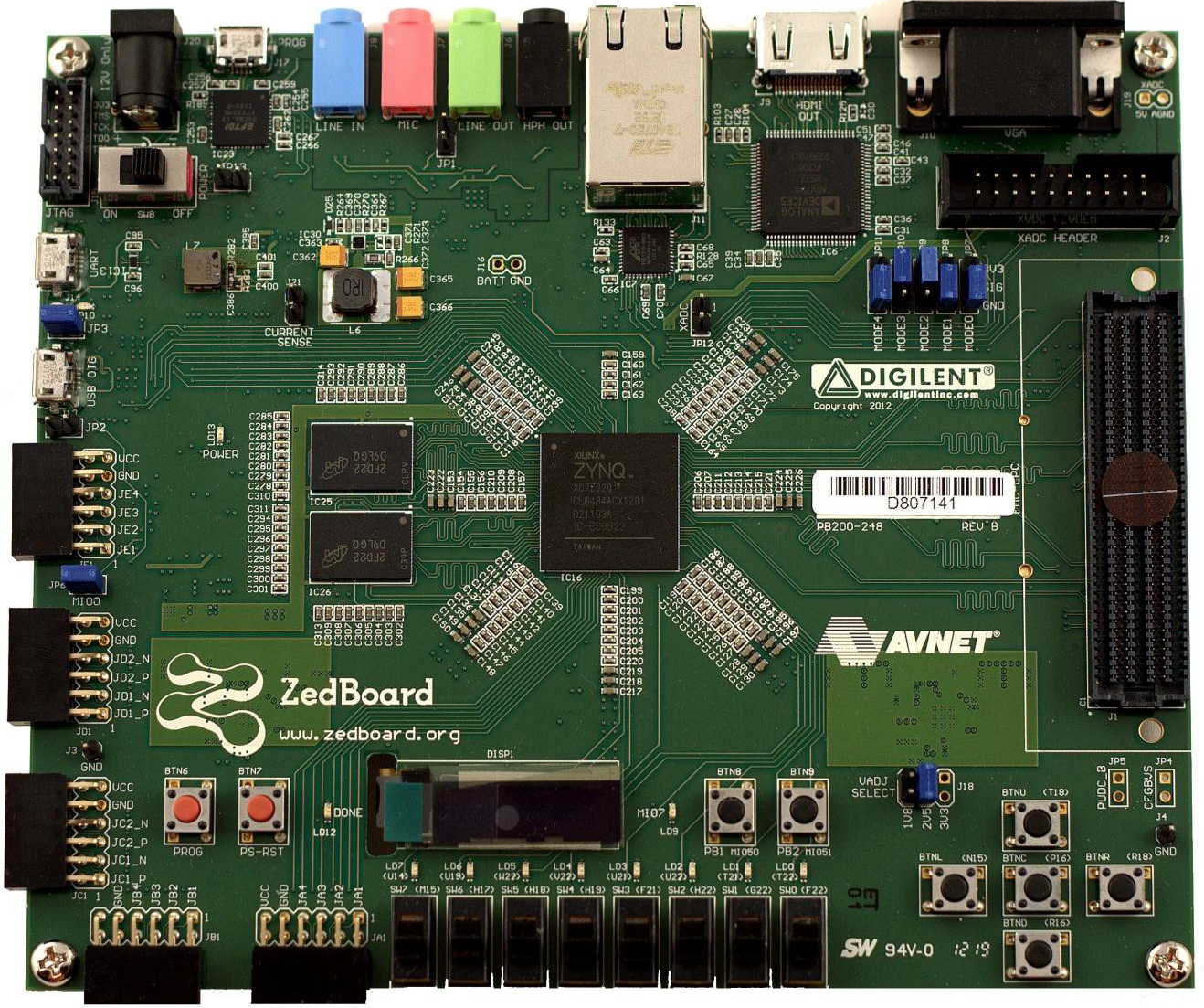
The ZedBoard should have the jumpers configured as per the image below + PLEASE ADD JP2 for OTG in HOST Mode to enable USB Power out:
This approach allows the project to connect to the various git repositories on line that are required and maintain links to the currently checked out versions of the third party libraries etc.
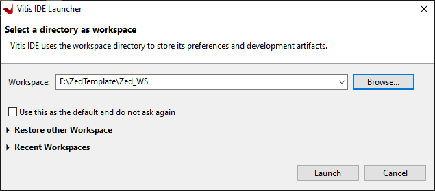
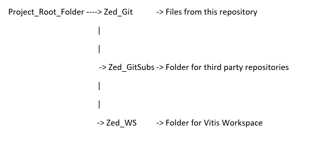
The project is set up to work with the following directory structure choosing your own name and location for the Project_Root_Folder(for this example we are using 'E:\ZedTemplate'), Note: the subfolder names must be as specified here for the relative paths to work in the Vitis environment):
Go ahead and create the root folder of your own name and path for the project and add the subfolders 'Zed_GitSubs' and 'Zed_WS' (Note: The 'Zed_Git' Folder will be created by Vitis later.)
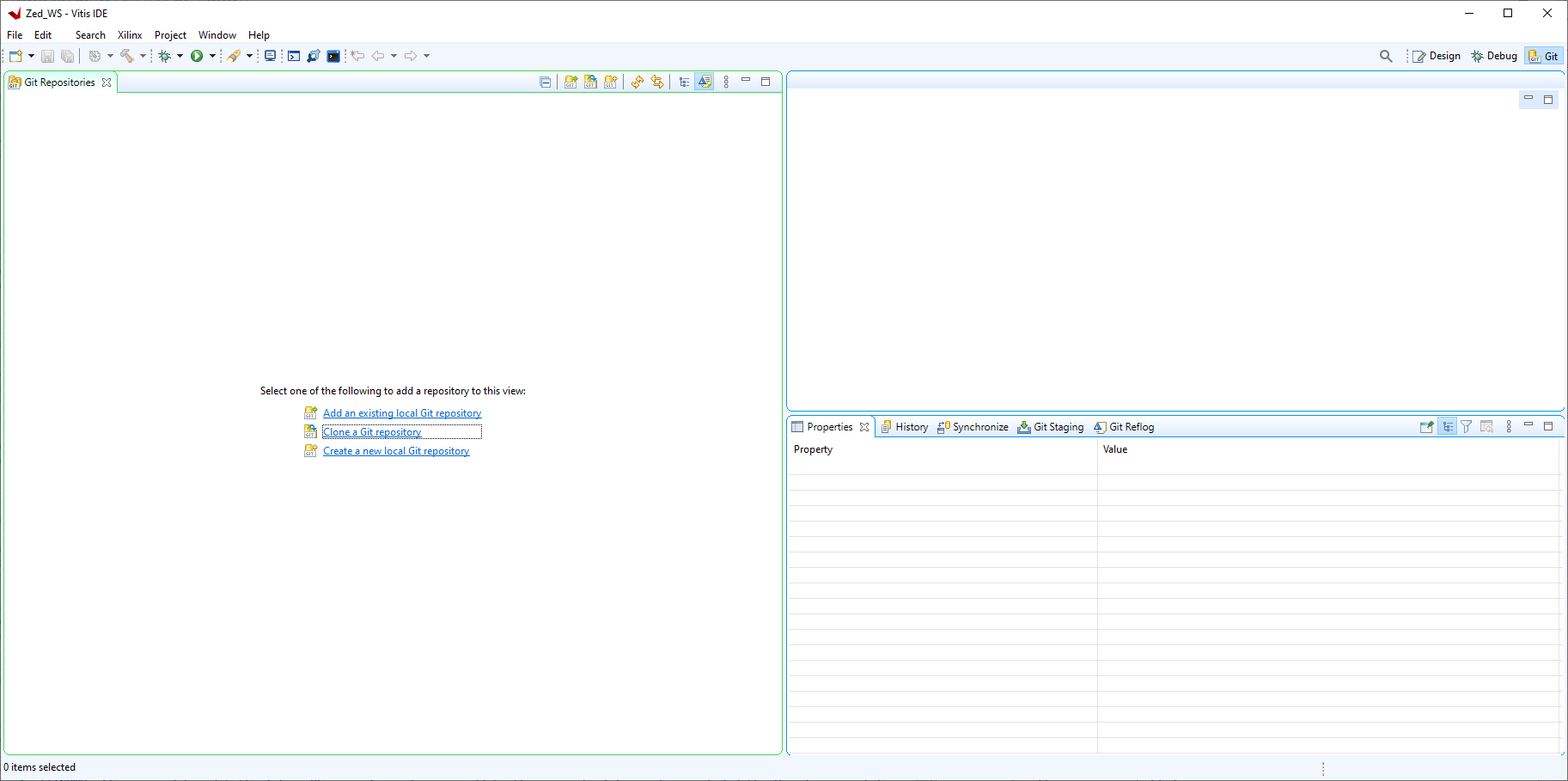
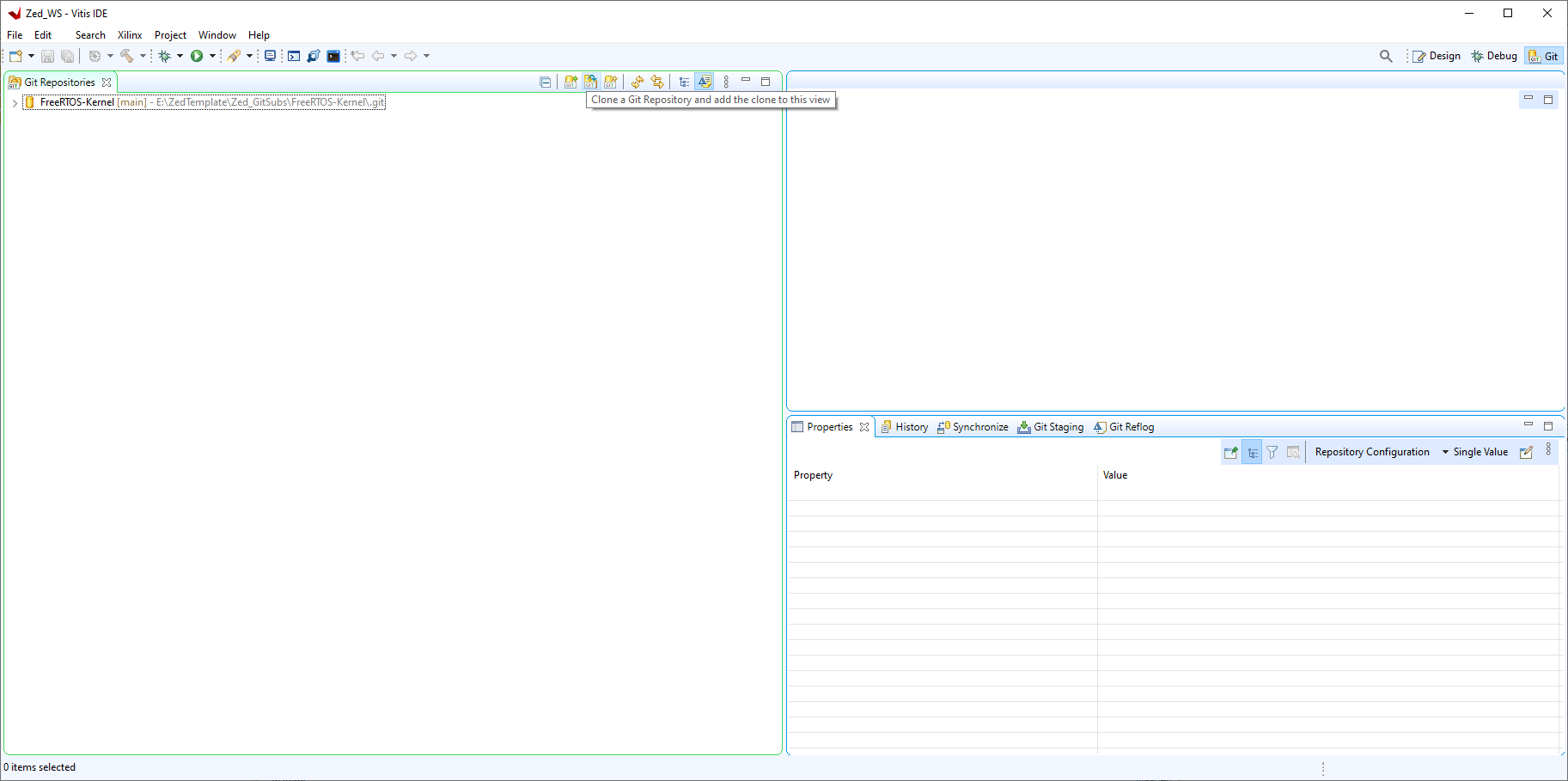
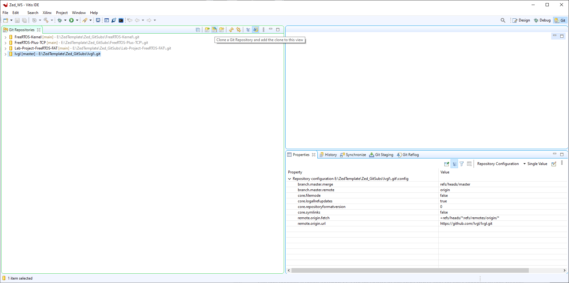
By selecting 'Clone a Git repository'(Tip: If you copy the url for the repository prior to clicking 'Clone a Git repository it will automatically fill in the next window for you):
Firstly the FreeRTOS Kernel
https://github.com/FreeRTOS/FreeRTOS-Kernel.git
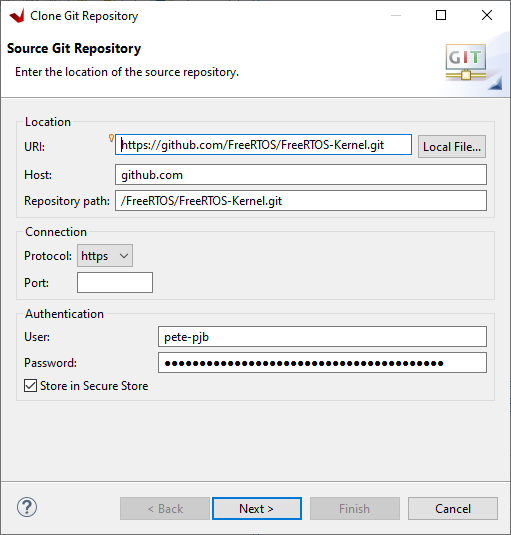
Click Next>
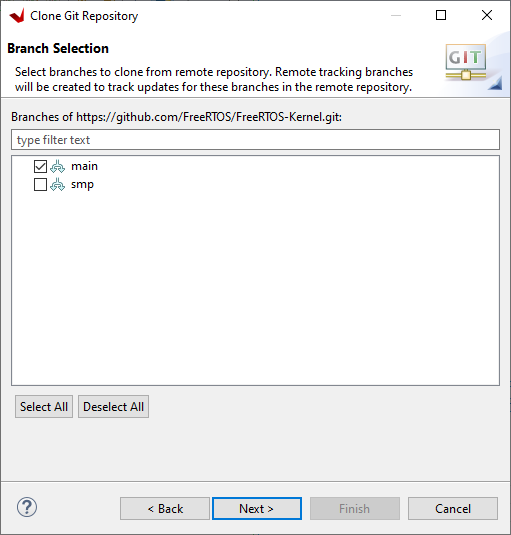
Select main branch and click Next>
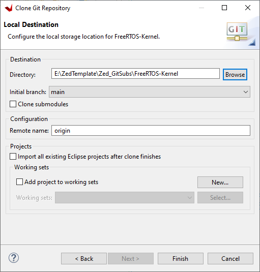
Select the path to the Zed_GitSubs directory click Finish>
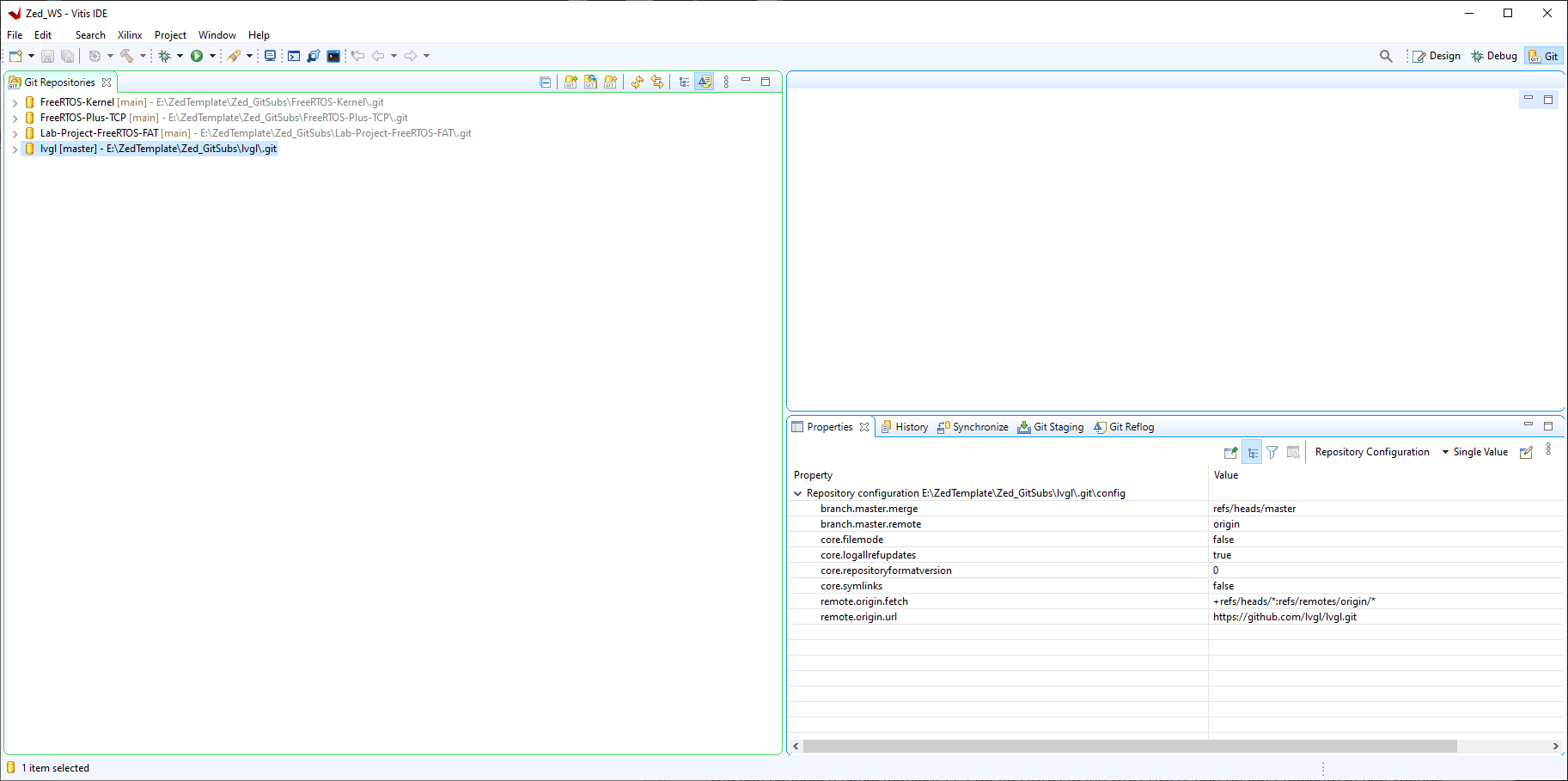
When the clone is complete you will see the repository in the list:
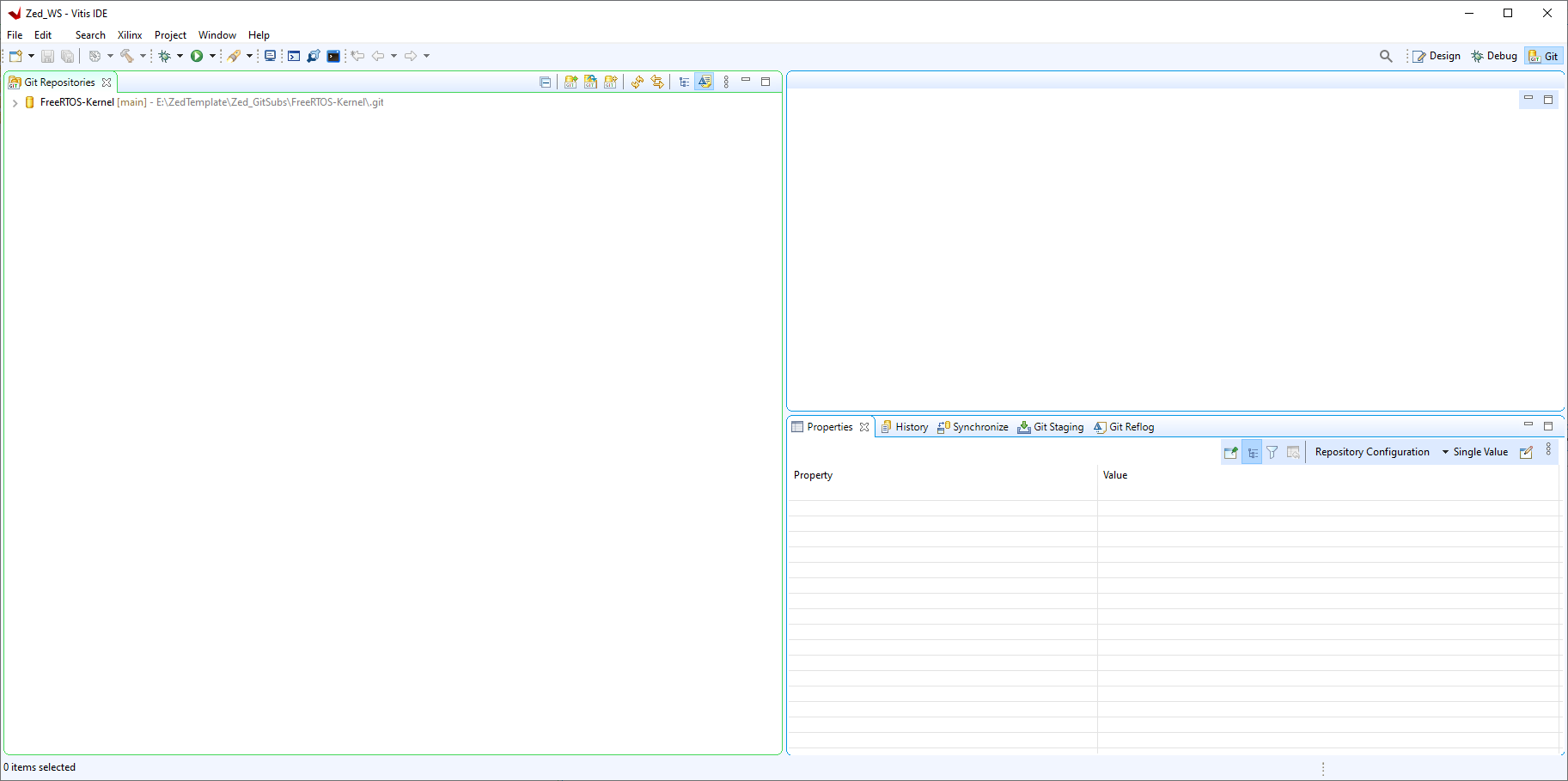
Now the FreeRTOS-Plus-TCP Module
https://github.com/FreeRTOS/FreeRTOS-Plus-TCP.git
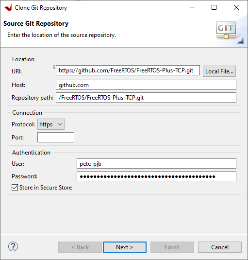
Click Next>
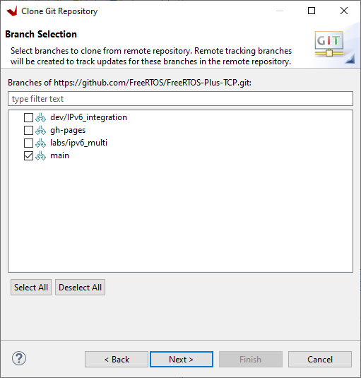
Select main and click Next>
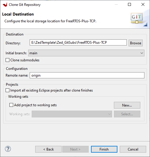
Select the path to the Zed_GitSubs directory click Finish>
When the clone is complete you will see the repository in the list:
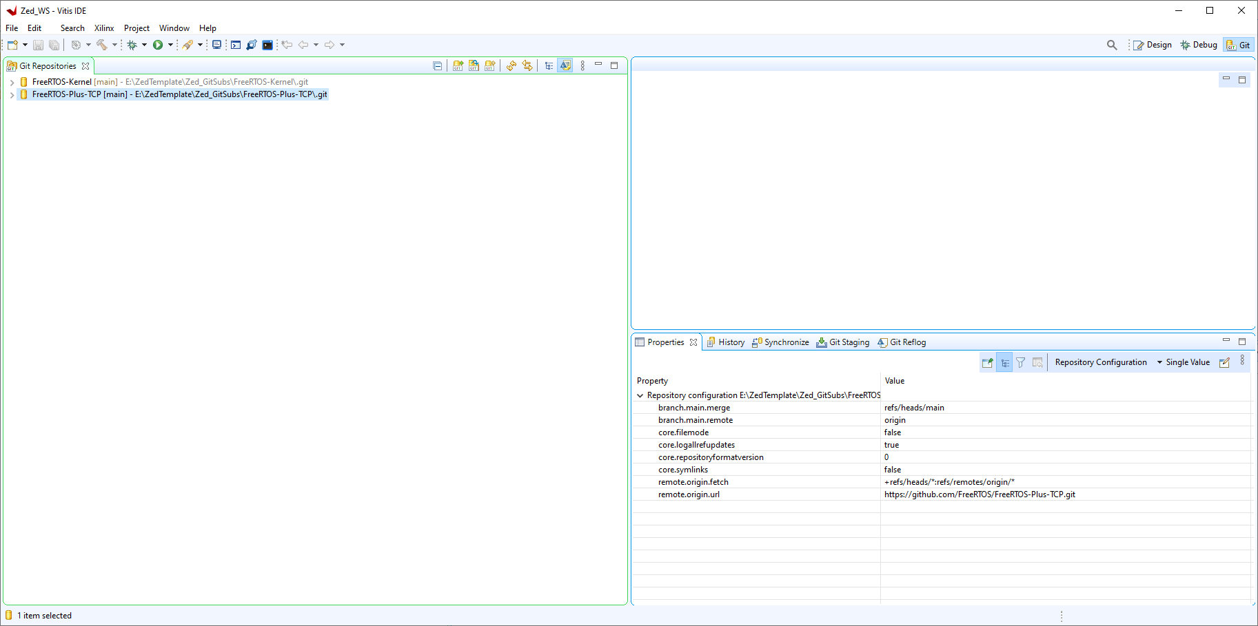
Now the Lab-Project-FreeRTOS-FAT Module
https://github.com/FreeRTOS/Lab-Project-FreeRTOS-FAT.git
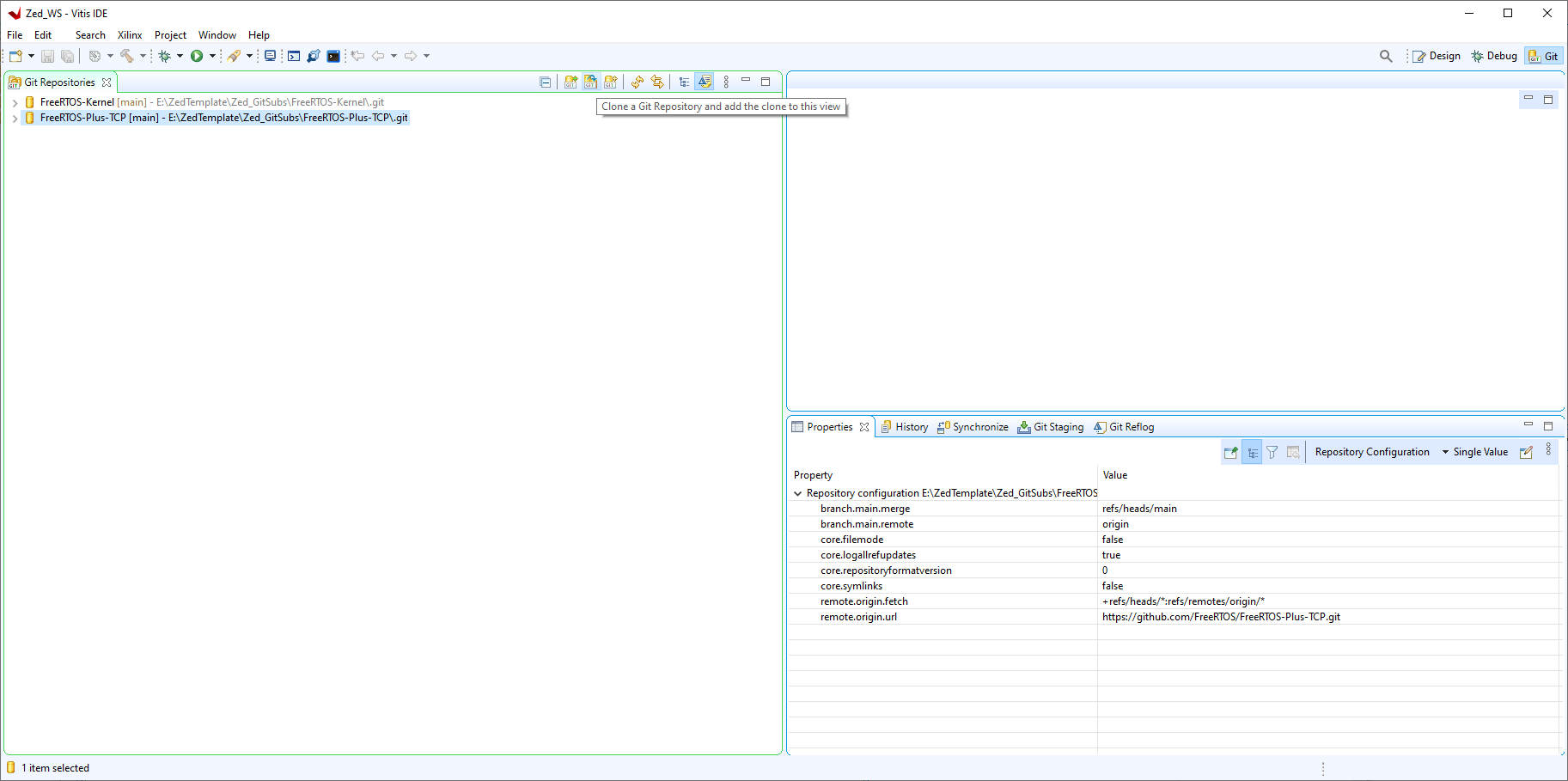
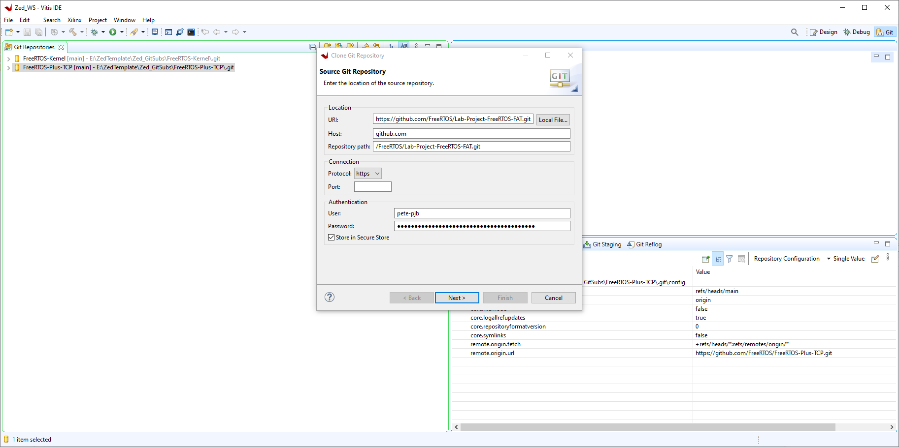
Click Next>
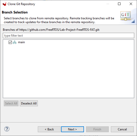
Select main and click Next>
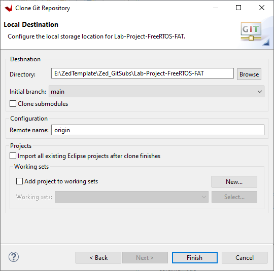
Select the path to the Zed_GitSubs directory click Finish>
When the clone is complete you will see the repository in the list:
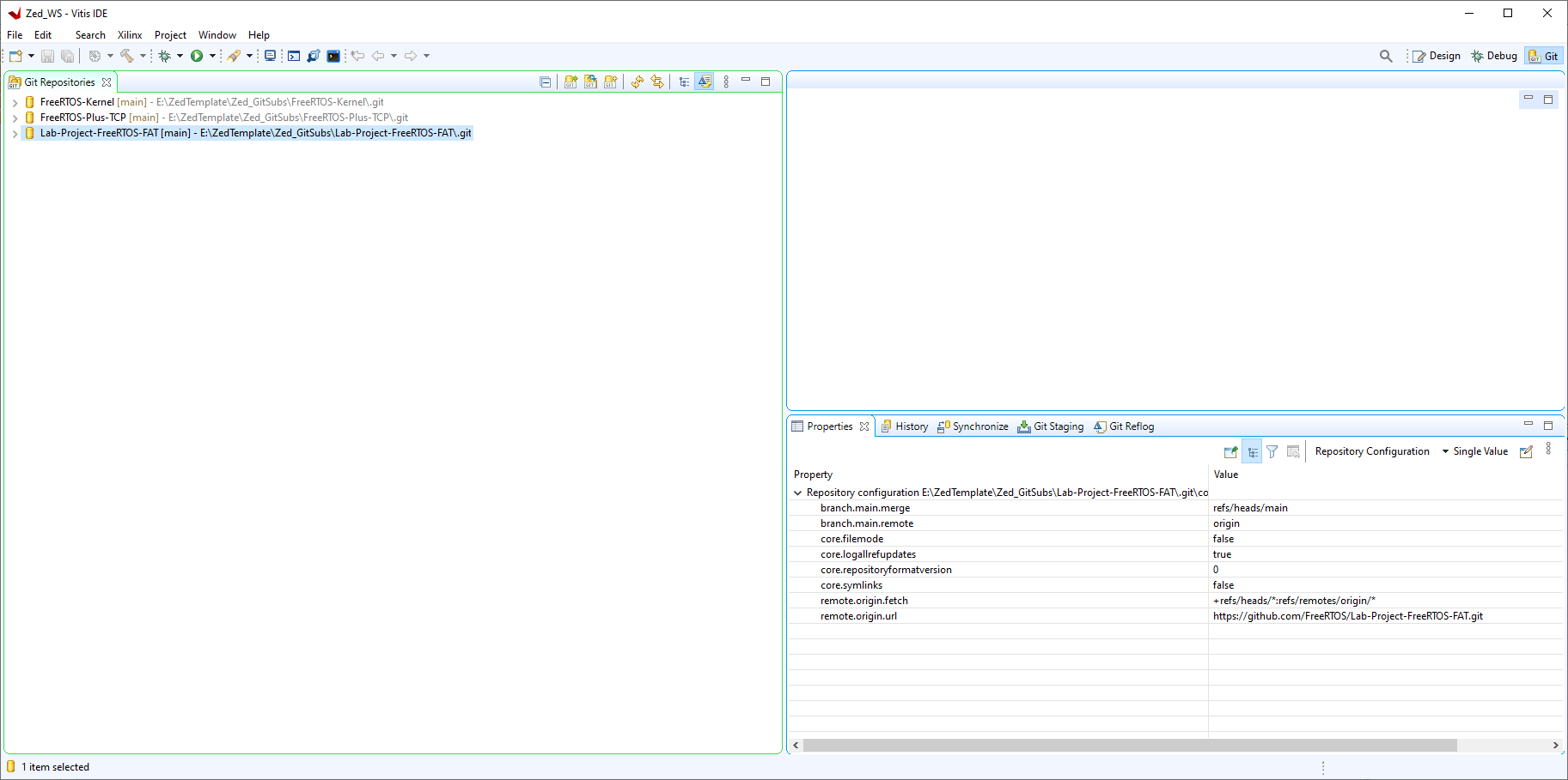
Now the LVGL library
https://github.com/lvgl/lvgl
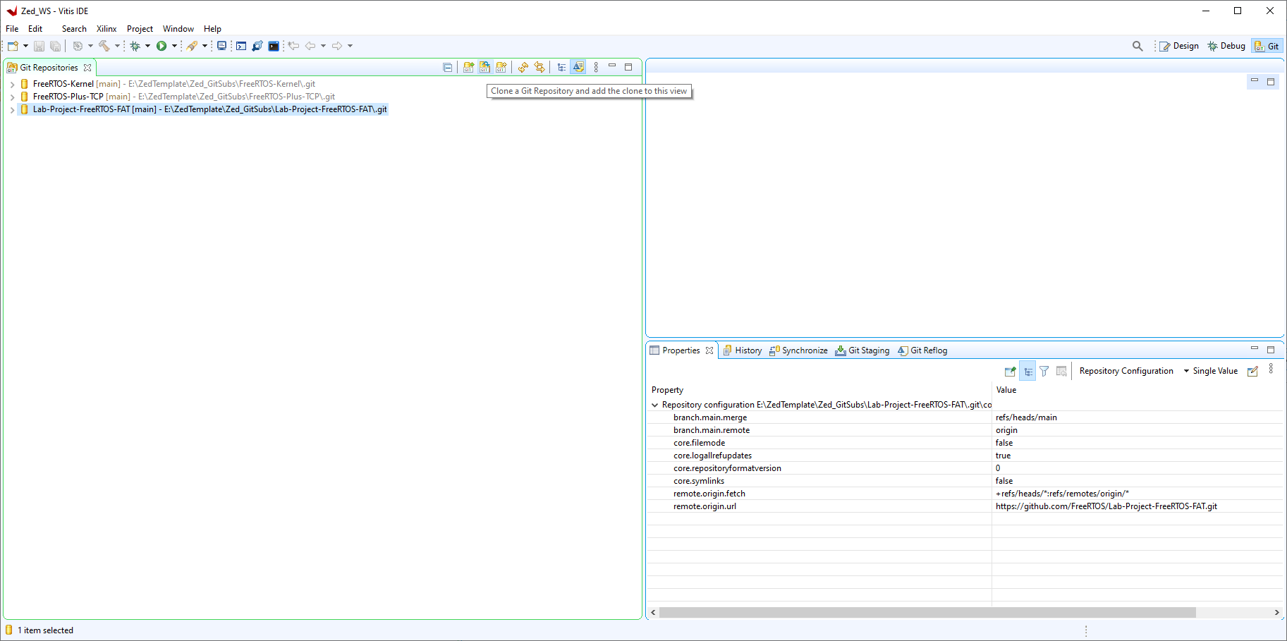
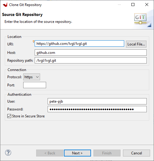
Click Next>
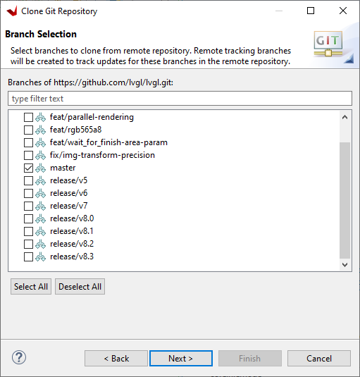
Select release/v8.3 (NOT MASTER FOR NOW! - Will update this once v9 becomes stable) and click Next>
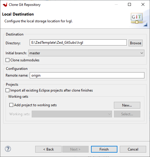
Select the path to the Zed_GitSubs directory click Finish>
When the clone is complete you will see the repository in the list:
https://github.com/pete-pjb/Zed_Git
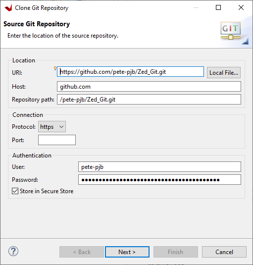
Click Next>
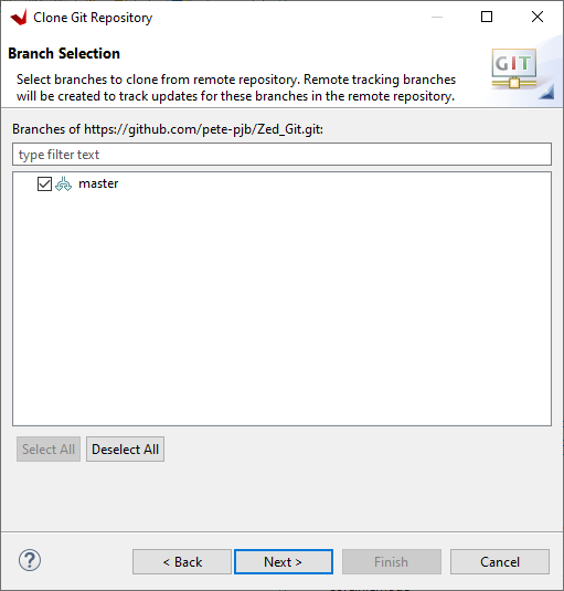
Select master and click Next>
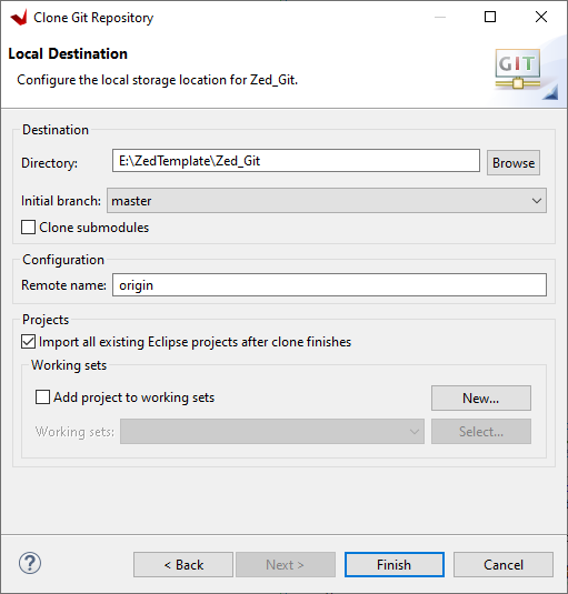
Select the path to the Zed_Git directory ie project_root_dir\Zed_Git and tick 'Import all existing Eclipse projects after clone finishes' click Finish>
When the clone is complete you will see the repository in the list:
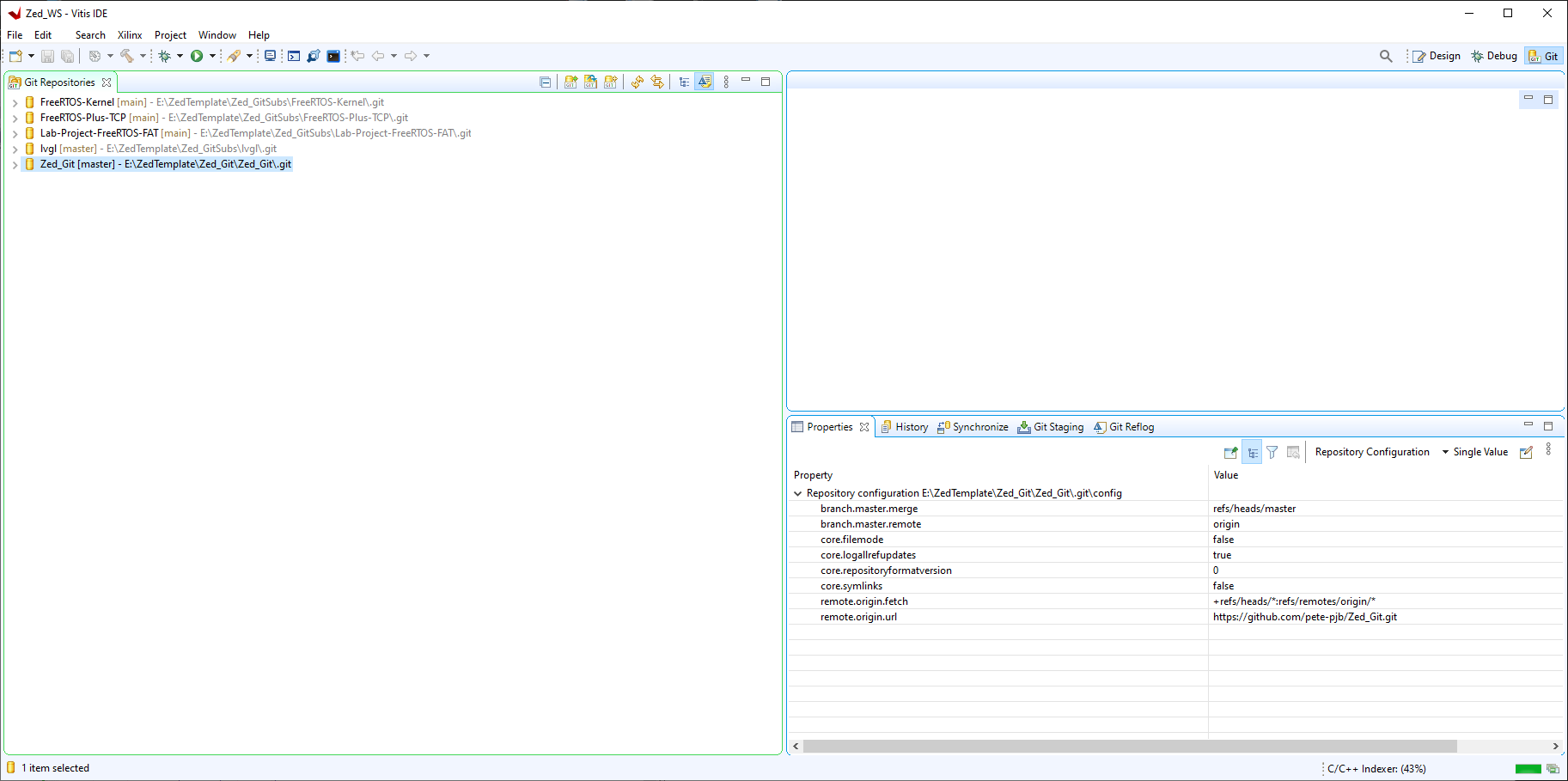
4. Open the C/C++ perspective in Vitis, expand the two projects in the root of the workspace and update the hardware specification.
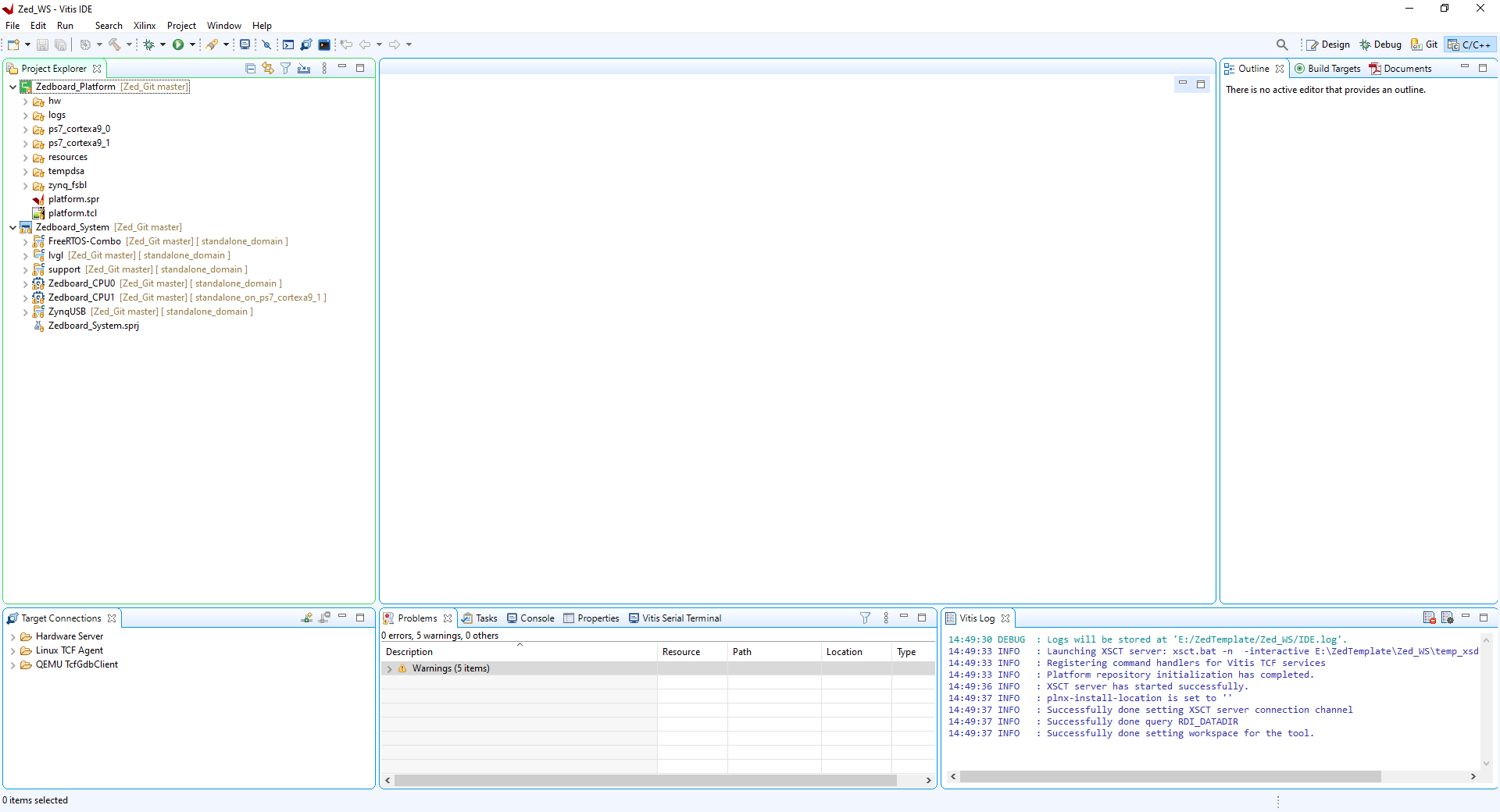
Right click on Zedboard_Platform and select 'Update Hardware Specification'
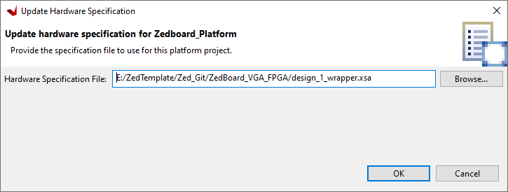
Enter the path to the platform 'design_1_wrapper.xsa' file in the box it is in the Zedboard_VGA_FPGA design folder. Now build the platform project.
This will generate an error:

Click 'Change referred platform'
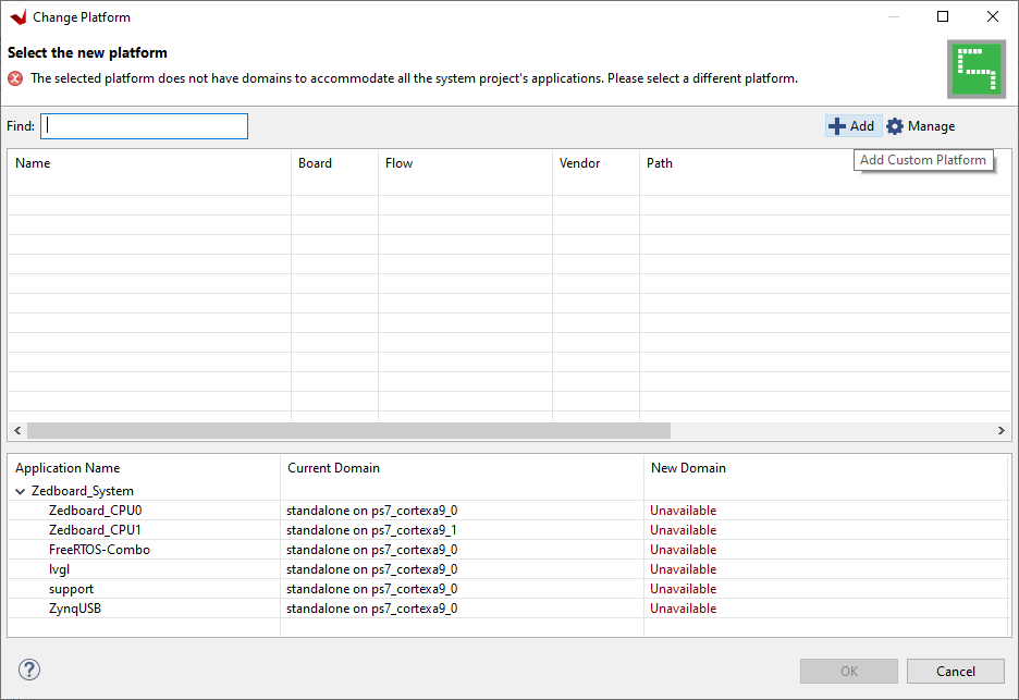
Click '+ Add'
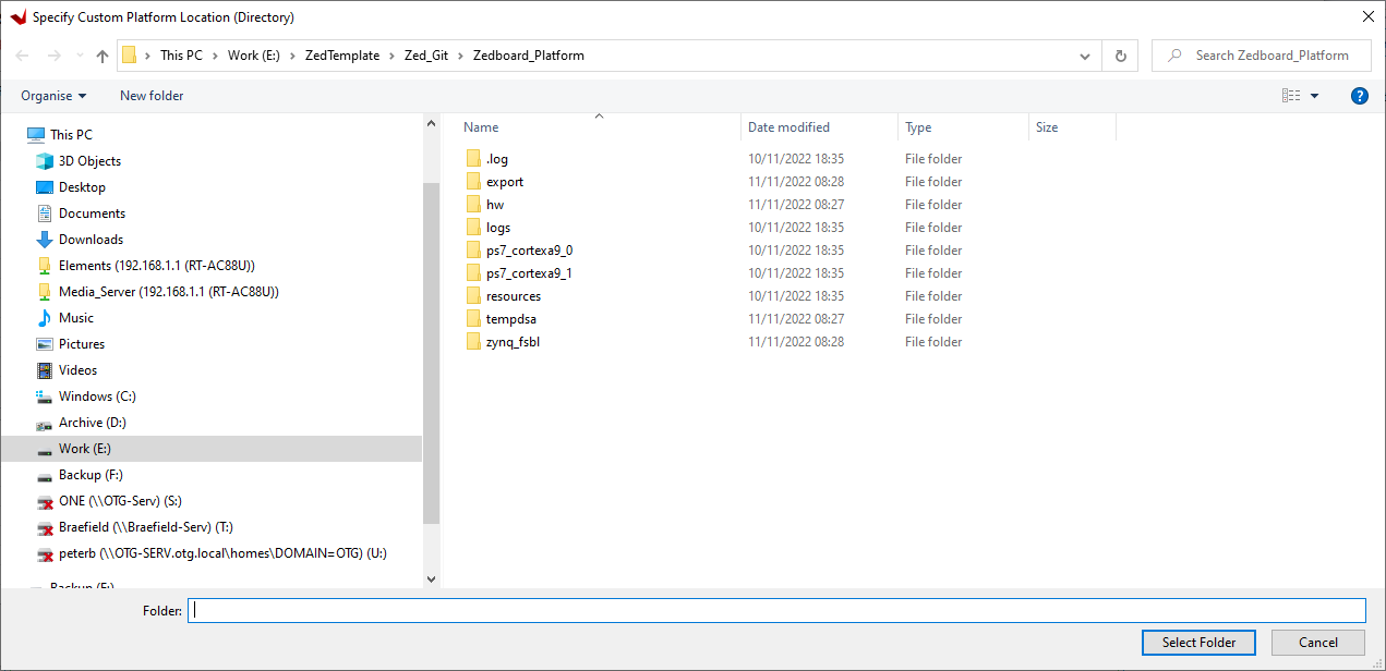
Select the path 'project_root_dir\Zed_Git\ZedBoard_Platform' and hit 'Select Folder' button.
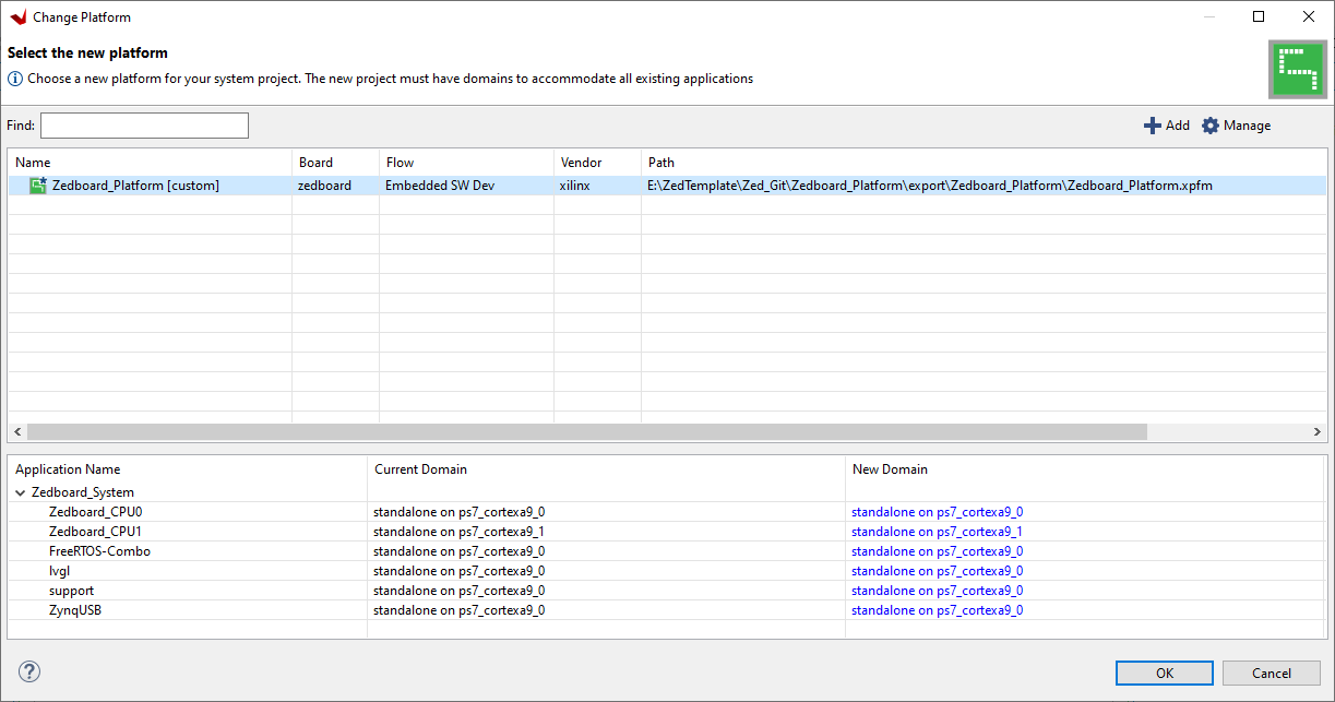
Select the ZedBoard_Platform[custom] entry in the table and hit 'OK'

Hit 'Yes' on the next message box to continue.
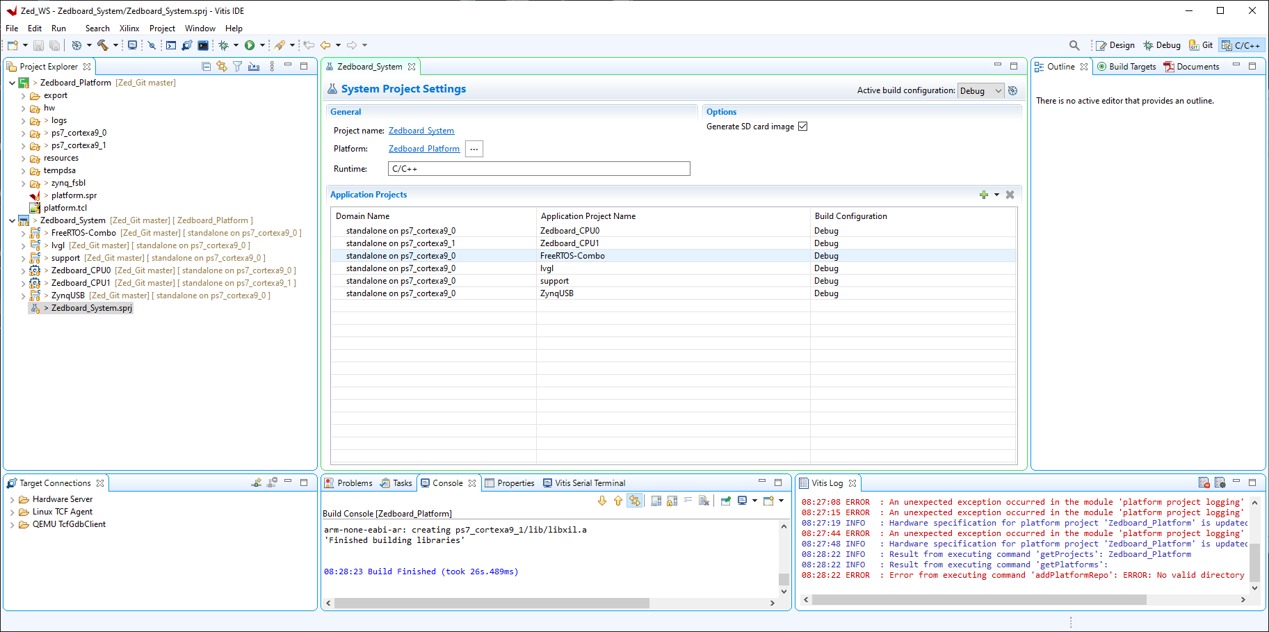
Note: You may also need to change the path specified by CFG_TUSB_OS_INC_PATH in tusb_config.h to your own FreeRTOS-Kernel/include path.
- Build 'FreeRTOS-Combo'. (FreeRTOS combined Kernel/TCP/FAT library)
- Build 'lvgl'. (LVGL Graphics Library)
- Build 'support'. (Home grown support library)
- Build 'ZynqUSB'. (Adapted version of TinyUSB library)
- Build 'Zedboard_CPU0'. (Project for ARM Core 0 Code)
- Build 'Zedboard_CPU1'. (Project for ARM Core 1 Code)
- Build 'Zedboard_System'. (System Project will generated BOOT.BIN file)
Note: There are a number of benign warnings generated during the project builds these can be safely ignored.
You are now ready to either create a debug session and load the code over jtag into the Zedboard the via 'PROG' USB connector.
Open Debug Configurations and highlight TCF Single Application Debug then click New launch configuration button:
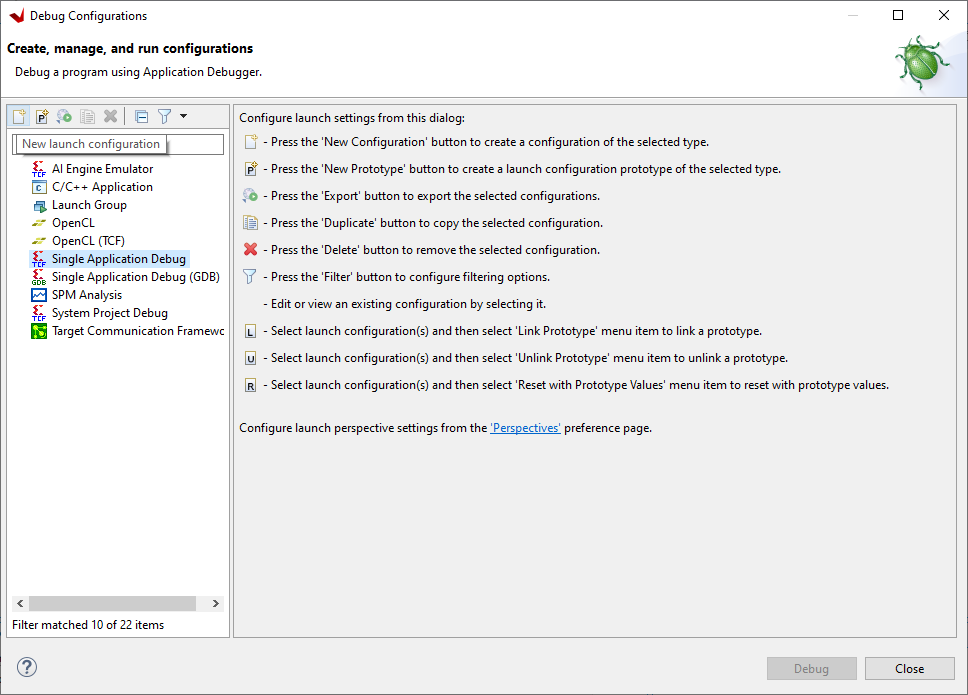
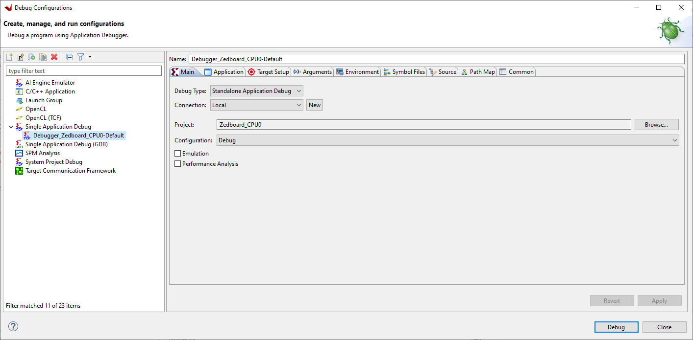
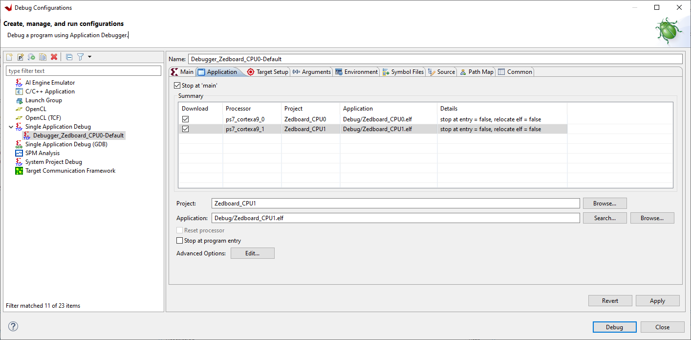
Click Application tab and tick ps7_cortexa9_1
Click Target Setup tab and check it looks like this:
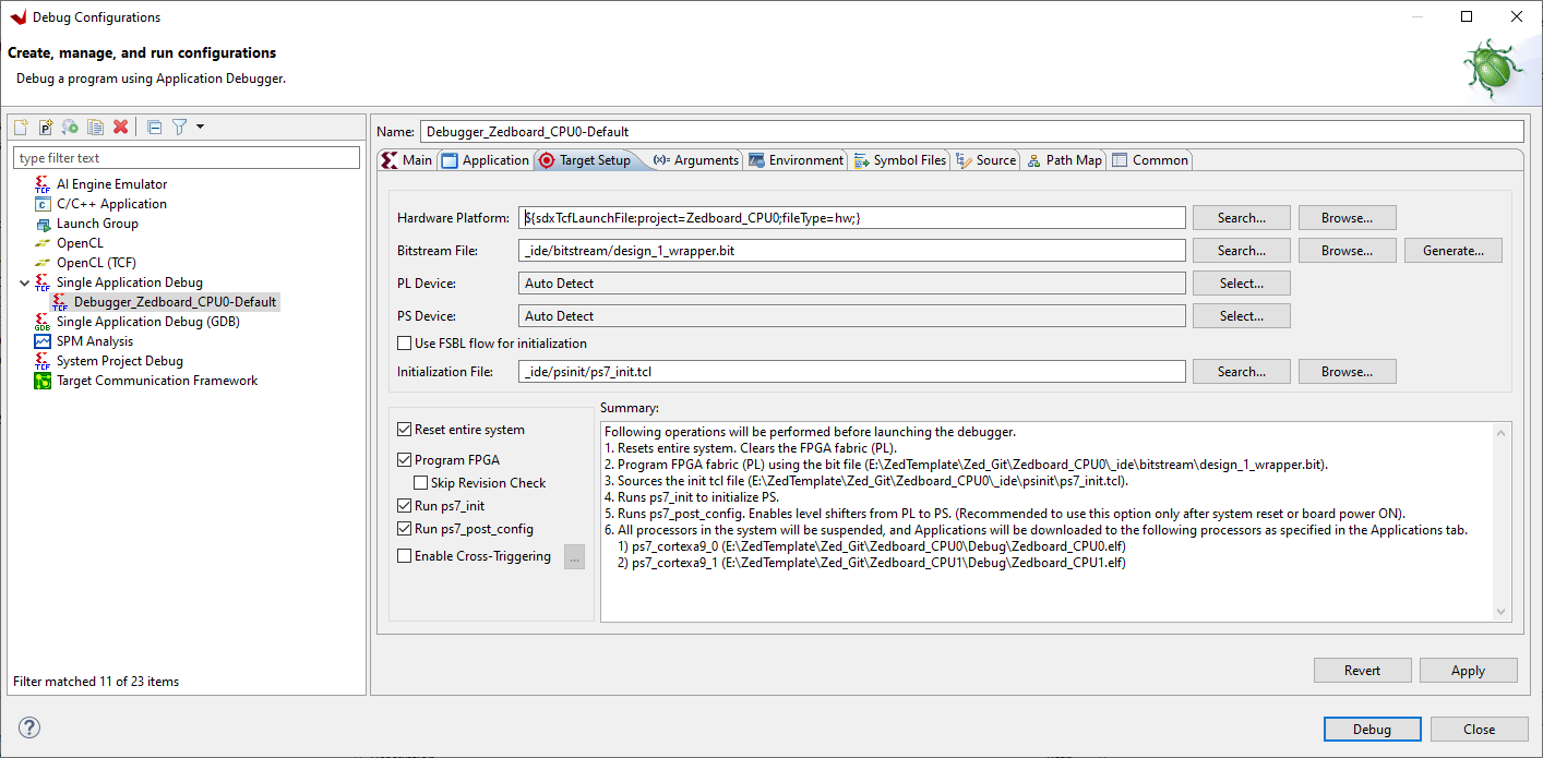
Now hit the 'Debug' button and the application will start, if the FPGA is running okay you will see the 8 LEDS on the Zedboard turn into an 8-bit binary counter and start flashing.
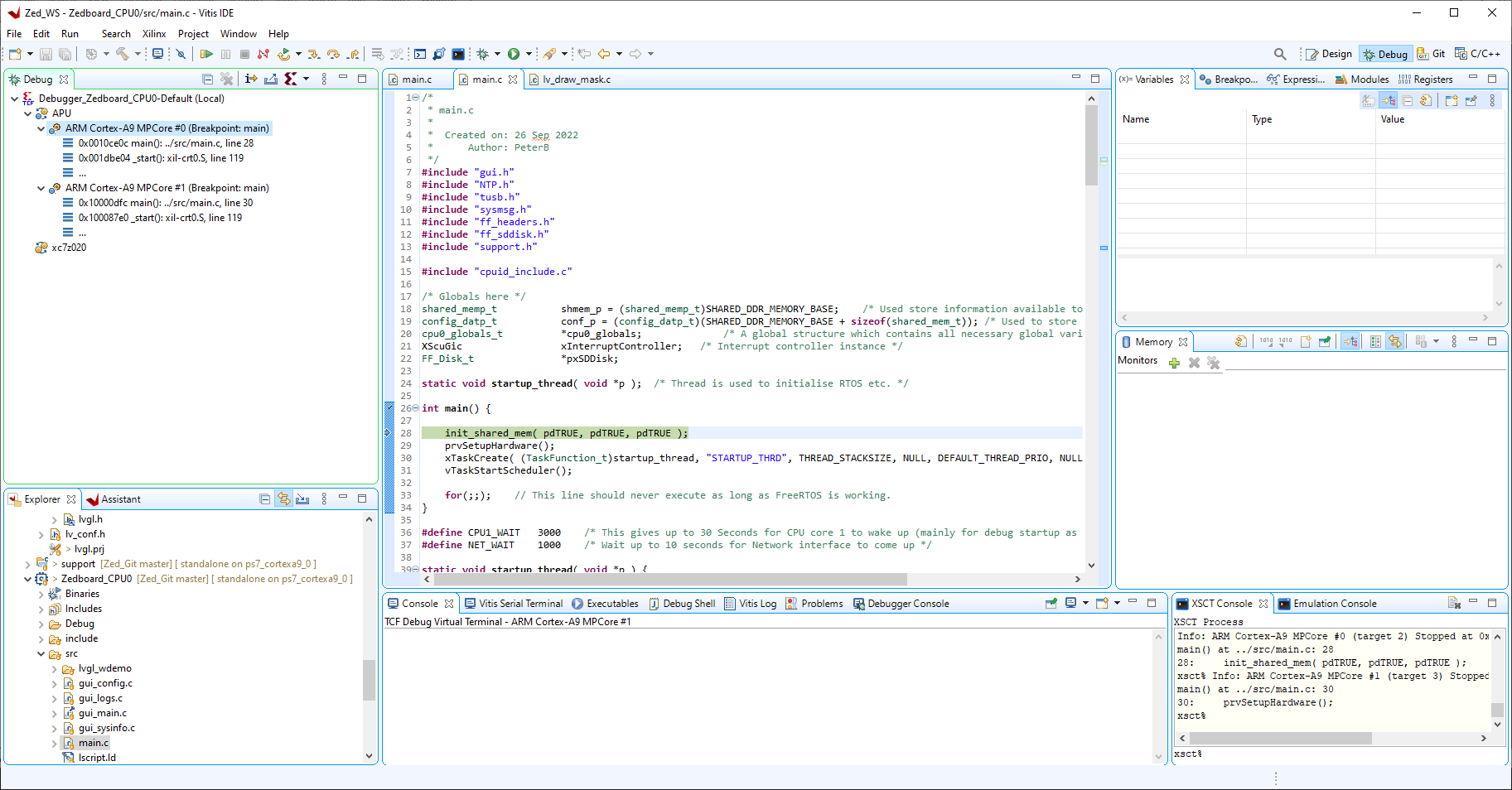
Now start the two cpu cores running, core 0 followed by core 1 (Note: wait a few seconds after starting core 0 before starting core 1), by clicking on each core under the APU entry in the debug window and pressing the Resume button, the software should begin to execute...
If you would prefer to just boot the system from the SD card you can copy the 'ZedBoard_System\Debug\sd_card\BOOT.BIN' file to the root of your SD card then insert it into the Zedboard power up and it should boot the project providing you have set jumpers on the Zedboard as mentioned at the beginning of this document.
You can connect a serial terminal @ 115200 BAUD (N 8 1) to the USB UART port on the Zedboard to see various status and debug messages during boot and operation.
NOTE: If you need to edit the fabric/Zynq configuration or add to the project, I have also included the Vivado project here in the folder 'Zedboard_VGA_FPGA' it is not easy to make this work well with Github and Vivado but if you take the folder structure and copy it to your work area and open the Vivado project it should work. You may need to set up the user repository so it can see the IP projects in the main folder.
