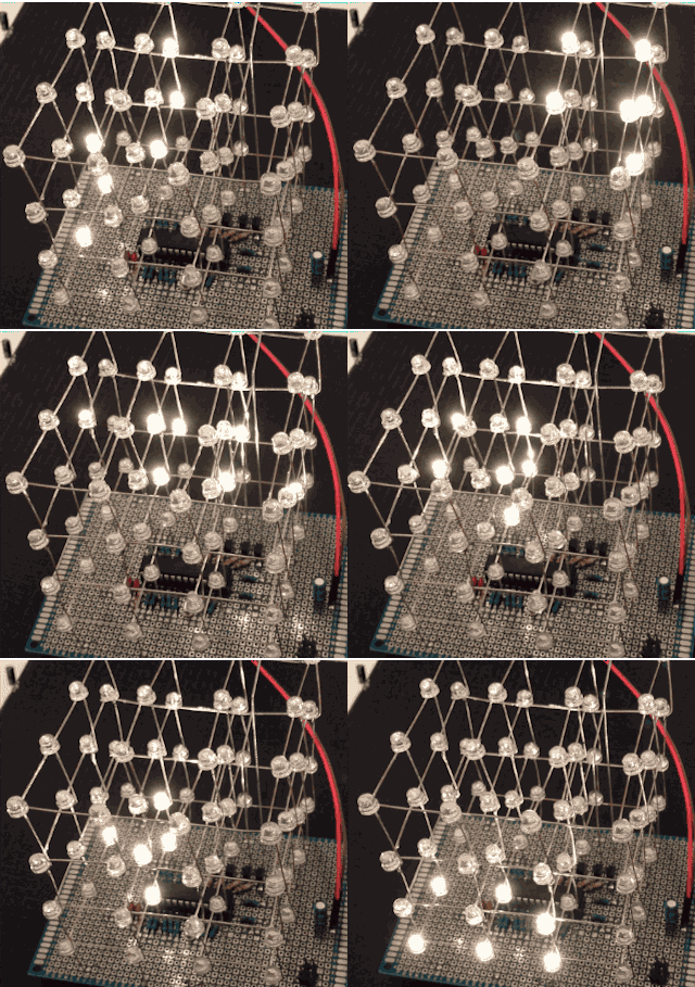
4x4x4 LED cube.
- Cathode per layer (4) driven low via PN2222 transistors.
- Anode per column (16) driven high directly.
- Protoboard 8x12cm (Microtivity).
- 64 x LED (warm-white, 5mm, CL562, 3.0-3.4v / 24mA max / 13,000 mcd, c-leds.com)
- 16 x 270 ohm resistors (for anodes).
- 4 x PN2222 transistors.
- 4 x 1K resistors (for transistor gates).
- 1 x 10K resistor (pull-up for AVR reset).
- 16 MHz crystal.
- 2 x 22 pF ceramic capacitors (for crystal).
- 10 uF electrolytic capacitor (power input).
- 0.1 uF ceramic capacitor (AVR decoupling).
- 22 gauge hook-up wire (too much).
- 2 pin male header for power.
TODO:
- Reset button?
- 6 pin male ISP header.
- ISP reset circuit?
One cathode layer at a time is driven low via a PN2222 transistor, whose gate is connected via 1K resistor to AVR port B bits 2..5. This maps to Arduino digital pins (...). It should co-exist with ISP functionality thanks to the 1K resistors (I hope?).
Each anode is driven directly by an AVR pin, via a 270 ohm resistor.
Code makes things happen. Multiplexing etc.
Regret: an 8x8 layout, instead of 4x16, could have been driven by a MAX2719 LED driver/multiplexer, saving lots of components and clock cycles. (Upside: 1/4 duty cycle is probably better than 1/8).
- AVR PORT B
- 0..1: Anodes 0..1 (Arduino digital 8..9).
- 2..5: Cathodes 0..3 + ISP (Arduino digital 10..13).
- 6..7: (crystal).
- AVR PORT C
- 0..5: Anodes 2..7 (Arduino analog 0..5)
- 6..7: (not available)
- AVR PORT D
- 0..7: Anodes 8..15 (8..F) (Arduino digital 0..7)
(top view)     (side view)
0  1  2  3    |-Cathode 0-|
4  5  6  7    |-Cathode 1-|
8  9  A  B    |-Cathode 2-|
C  D  E  F    |-Cathode 3-|
