Filament path is not straight through Bondtech wheels
RH-Dreambox opened this issue · 30 comments
The filament should, according to me, have a completely straight path through the Exrtuder unit.
When I check the MK3 extruder, it seems that the extruder motor is seated 0.5 mm laterally.
This means that the filament must be bent slightly to pass the engine's Bondtech pulley.
The center distance between the two Bontech wheels should be 9 mm and the center distance is determined by the two gear wheels (module 0.5).
The Bondtech gears can not be pushed together so it is a risk that you twist the extruder idler if is tightened too much.
The measurements are taken from Prusas download files.
https://shop.prusa3d.com/forum/original-prusa-i3-mk3-f30/fine-tune-your-e-axis-t13930.html
It seems that this issue contributes to problems with flexible filament.
Two users tried to fix it and so far it seems to work well:
https://shop.prusa3d.com/forum/original-prusa-i3-mk3-f30/any-ideas-how-to-get-this-flexable-material-to-pri-t14765.html
Can we hope for an official update in the future?
After some analysis in the thread mentioned by @ulfertg (check page 8 and 9) we found that the sweet spot for the gear spacing should be 8.5mm. This means a move of 0.25mm from original Prusa extruder.
Always thought this is the major flaw and cause of many problems. Stepper screws "just" need to be shifted along with the counterpart where the other side of the gear is... I tried it and gave up with openscad. Its a terrible adjustment but it needs to be done.
@chhu Stepper screws "just" need to be shifted along with the counterpart where the other side of the gear is.
This would affect two parts: the Extruder Body, and the X-Axis Carriage. The modeling is the "easy" part - but you'd need to mess physically with the X-Carriage itself, which is painful.
The other alternative would be to move the entire filament path (affecting the Extruder Body and the Extruder Cover) the same amount (leaving the position of the stepper motor in place). It's more modeling work, but the fix should be easier to actually accomplish after the modeling work is done.
Some good news: I've done the remodeling work already!
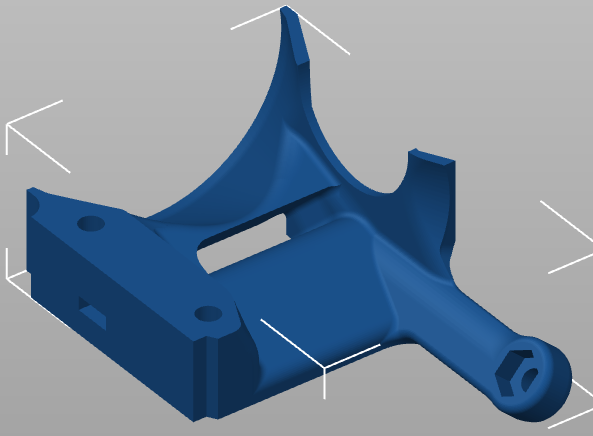
"N3" Extruder Parts
I ended up finding an 8.7 mm bondtech alignment sweet spot in the perfect land of CAD models. This results in a move of 0.35 mm of the filament path (about halfway between @gregsaun 's suggestion of 0.25 mm and @RH-Dreambox 's suggestion of 0.5mm:
I've printed this and have been using it for several months now (since August) and it has been fantastic to print everything quietly. I also suspect that this would help with flexible filaments, but haven't had the chance to test.
If you print these parts, let me know - I'd love to hear if this actually fixes your issues as well.
I did notice that with R3 the issue does not go away.
Since Prusa was made aware of this already in January, I thought thex would have fixed it by now?
Maybe Prusa can comment if they changed anything?
Not changed at all, R3 is still having this issue. I could confirm with Bondtech that the optimal gear spacing is 8.5mm
Same here, one of the first Bear extruder feature :-D
I can confirm that my CAD program indicates that the cc distance between two gears with module 0.5 mm and 17 teeth is 8.5 mm. (Not 9 mm which I previously incorrectly stated)
@Spacemarine2018 - the filament path hasn't changed from the R2/B6 parts (January timeframe) to the R3/B7 (current) parts. See this forum post from Nathan.d2 (who seemed to do some of the work and modeling of the R3 parts):
This diameter and location of filament path was not changed from last version. Just bottom was made closer to the gears, but NOT changed in diameter or location.
@jltx1 & @gregsaun - I'm a big fan of both the Skelestruder and the Bear designs, and assumed this had been addressed in them given how well thought out they appear.
@gregsaun & @RH-Dreambox - I agree that the nominal axis spacing between the gears for proper gear tooth engagement is 8.5 mm. However, I'm not convinced that this spacing would be maintained once filament is inserted between the drivegears.
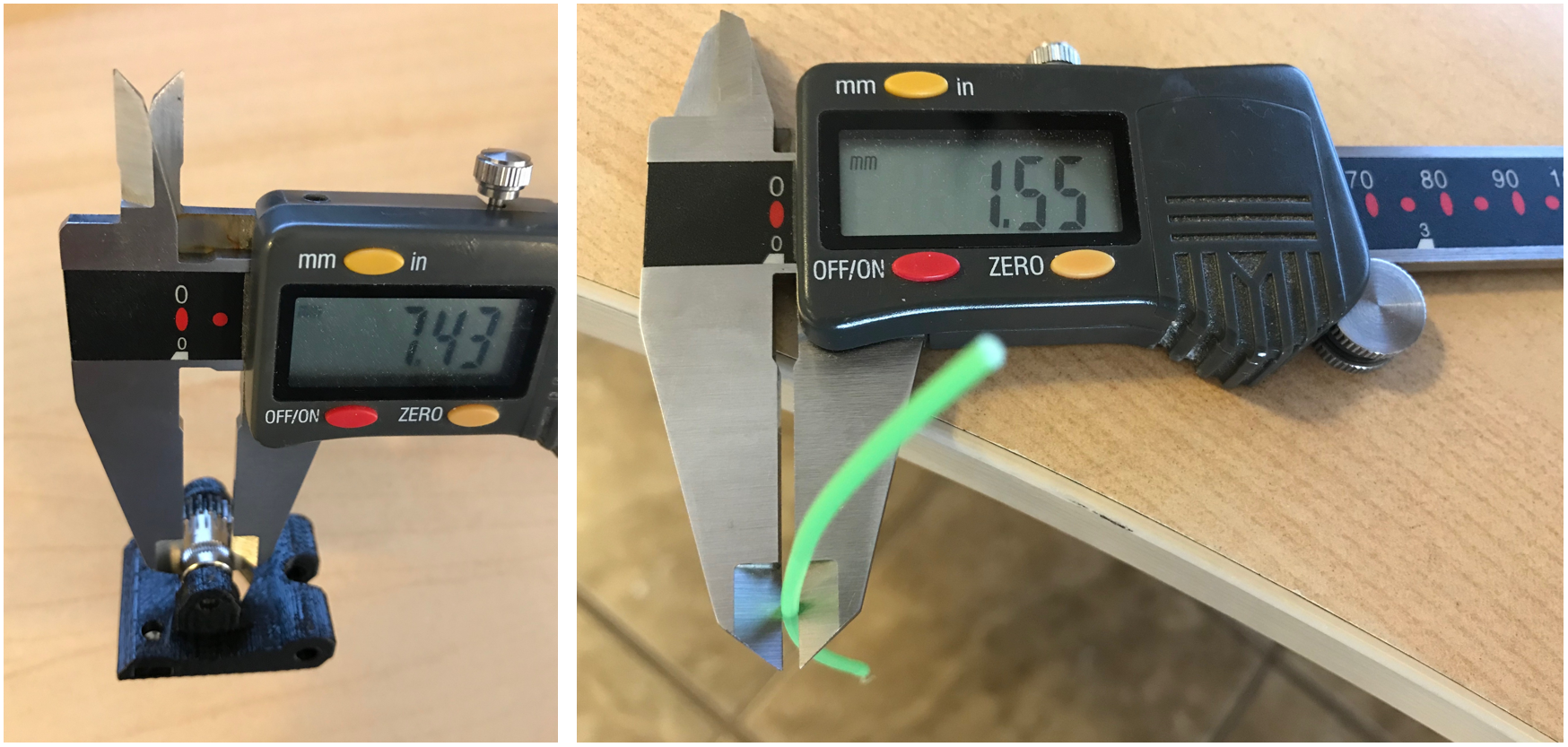
My idler (and I'm assuming drive-side as well) measures 7.4 mm diameter at the hobbed teeth. It's probably fair to be generous and assume somewhere around 7.2 mm once the hobbed teeth "cut" into the filament.
I was able to compress a strand of PLA filament down to 1.55 mm by using a surprisingly high amount of force by hand with the sharp part of my calipers. I think under any normal circumstances, it would not be feasible for the idler tensioner springs to provide this force, but again one could be generous and say that the filament diameter would be compressed into an oval shape with a small diameter of 1.5 mm.
That means that under probably the most generous case (which is what I modeled my parts linked above to), the actual spacing between the axes would be 7.2 mm + 1.5 mm = 8.7 mm. In real life, the actual spacing is probably closer to 9.0 mm (7.35 mm hobbed tooth diameter +1.65 mm compressed/cut filament diameter).
I just don't see a way that an 8.5 mm spacing could be maintained once filament is inserted with these parts and this geometry.
@uscbutterworth the gear on the motor will not move, and so the filament position, and so the filament path. In reality the filament will move a bit because some plastic are harder than others and teeth will bite at different depth.
You are right, the gear spacing will change but only the idler will move. Gear spacing is still an important value because it determines the position of the "non-moving gear" (the one on the motor) which will be half of gear spacing.
Gear spacing is 8.5mm according to Bondtech. They have defined this value after testing tons of filament and found that this is the sweet spot to "match them all".
the gear on the motor will not move, and so the filament position, and so the filament path. In reality the filament will move a bit
the gear spacing will change but only the idler will move.
Yep, agreed.
the position of the "non-moving gear" (the one on the motor) which will be half of gear spacing.
I think I may be picturing things differently here. It was helpful for me to mentally set the non-moving gear (motor) axis to "zero", and work backwards from there.
First, I want to say that I have no problems with the 8.5 mm gear spacing - the bondtech gears themselves have been just fine for me.
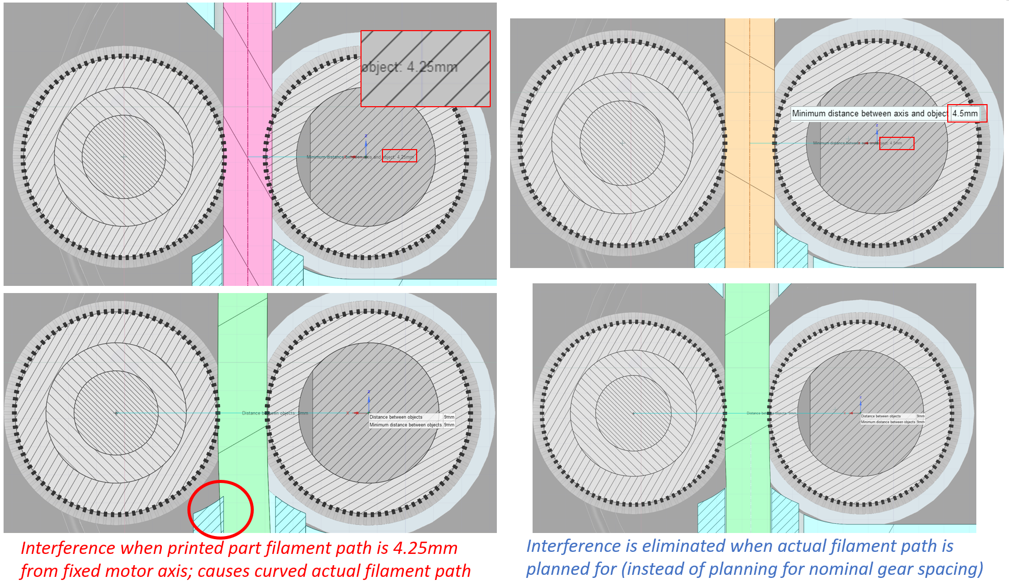
If the printed part filament path is placed at the midpoint between the two gears, it's going to be at 4.25 mm from the motor axis (see the image above, left side, pink indicates nominal printed part filament path). Once filament is loaded and the idler gear moves outward, the actual filament path also moves outward, and results in interference with the printed part filament path and the teflon tubes.
Another way to phrase this: if the printed part filament path is optimized for the 4.25 mm position, the filament and idler can only move outward since the bondtech gears will never be closer than 8.5 mm apart.
It would probably be more optimal to align the printed part filament path with what will cause the filament to be straight when filament is actually inserted - in other words, building in tolerance to allow filament to move both inward and outward (left and right in these views).
That printed part filament path position ends up being about half of 8.7mm to 9.0mm spacing once the bondtech gears are moved apart to accommodate the filament (again, this is a good thing, and I have no problems with the 8.5 mm nominal gear spacing): that means the axis of the filament path holes in the printed part must be located somewhere around 4.35 mm to 4.50 mm from the motor shaft axis.
Brief update post-Mk3S release. The R4/Mk3S parts still have the same 4.00mm motor shaft/bondtech drive gear to printed part filament path spacing as the R3 and previous parts. I have modified the R4 parts to an "N4" version, again with 4.35mm bondtech-filament path spacing, and posted them here:
https://www.myminifactory.com/object/3d-print-86329
@uscbutterworth
Can you comment on the difference in hole diameter between the extruder body (2.4mm) and the adapter-printer (2.6mm). It looks like a good spot for a snag, especially with the MMU.
I plan on moving the hole to 4.35 and eliminating the adapter since for the MMU it looks to have no purpose. What do you think the hole did should be?

This image shows the mmu2s version of the adapter-printer but the other appears similar. (Can't tell for sure because the step I have is messed up.)
I agree, it seems odd (i.e., not perfect), but in practice doesn't seem likely to cause any issue. You'd probably be hard pressed to find a filament with less than 100 micron worth of rounding at the tip unless it has been freshly cut square (instead of at an angle as recommended). If you're really concerned about a snag at that point, take a countersink drill bit and just give it a few finger twists to deburr and remove the concerning edges.
Either 2.4mm or 2.6mm dia hole/path seems to work fine above the bondtech gears in my experience. I'll usually add a 0.4 mm chamfer on both sides of a cylindrical gap like that in my model, so I can skip the countersink/deburring step mentioned above.
The purpose of the adapter part would be simply to occupy space and make the rest of the parts compatible with a non-mmu2S setup or with the mmu2S. If you're only using the MMU2S (and plan to keep it that way), there's probably no harm in eliminating this part.
@uscbutterworth
Thanks for your input.
Brief update post-Mk3S release. The R4/Mk3S parts still have the same 4.00mm motor shaft/bondtech drive gear to printed part filament path spacing as the R3 and previous parts. I have modified the R4 parts to an "N4" version, again with 4.35mm bondtech-filament path spacing, and posted them here:
https://www.myminifactory.com/object/3d-print-86329
Thanks for the new N4A parts!
I'm glad that there is flexible filament working good :-)
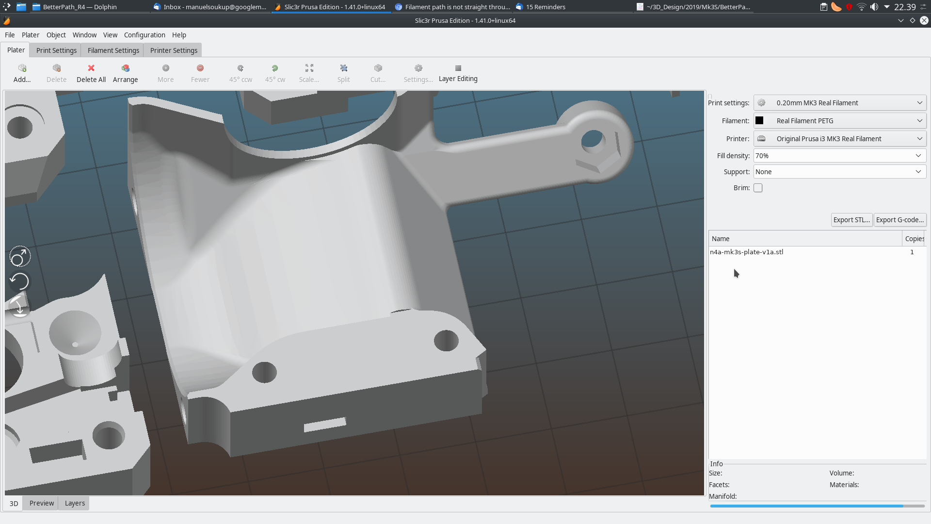
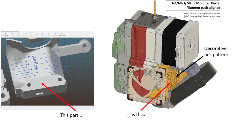
However i wanted to try the "Airflow" variant and noticed that the extruder cover is bloking the octoweb of the airflow. So basicly there is no air getting into to extruder on the side.
We're a bit off-topic for this particular github issue at this point. I'd love to continue talking about my part designs and the R4 part designs unrelated to the filament path alignment, but let's do that somewhere else.
I've posted my design here on the Prusa forum: https://shop.prusa3d.com/forum/user-mods-octoprint-enclosures-nozzles--f65/modified-c1-r4-mk3s-parts-better-filament-path-and-t28334.html - relevant discussion could happen there instead. Thanks!
@prusa3d-bb: has this been fixed in R5?
@mietek This is still not fixed in R5. Note that the stepper can also be moved a little around his mount which can contribute to make this problem worse. So a fixed path will only reduce the chance to be offset but will not solve it completely. If you look at fixing this then you need to have a self-centering stepper jointure as well as a correctly aligned filament path, this has been implemented in Bear extruder in case you are searching for a solution. Note that on R5 you need to self-align stepper as well as extruder-motor-plate as it is a split extruder body.
@gregsaun: Thanks. By “stepper” do you mean “idler”?
I looked into Bear, and I would prefer to avoid having to replace the entire extruder and the X axis in the hopes of fixing my problem. My newly built Original Prusa i3 MK3S cannot print using Fillamentum TPE 90A — it jams while loading the filament or soon afterward.
Does anyone have a fixed remix of the R5 extruder parts?
@mietek stepper equals motor, in this case the extruder motor. We call those motors "steppers" because they work by little steps (200 for a complete revolution on the Prusa motors).
I do understand you don't want to replace the entire extruder and I would only recommend if you are comfortable with modifying your printer.
What you can try is to move the extruder motor a little to the right (or to the left) while tightening. This will offset the gear. I don't remember if you have to move it to right or left unfortunately.
Note that in addition to making printing flexible filament a little more difficult it is also generating a "squeaky" noise with some filaments like PETG.
Unfortunately I don't think we will see a fix or an explanation for this issue from Prusa, it is now almost 2.5 years and 5 revisions of the extruder since it has been reported.
After having trouble with Flex and trying almost everything else. I've ended up at this PR. The offset fix helps greatly. However, when printing for a long time I’m having trouble with the airflow guides around the PINDA getting soft (not the PINDA Holder itself). Comparing R4 with R5 Prusa doubled the wall thickness. I’m aware that it is a huge effort to add R4 -> R5 changes to all parts. But an upgraded N4 at the PINDA area would be great.
A number of smaller changes occurred around and in the extruder. The filament path is slightly altered with the aim to make printing (especially flexible materials) more reliable.
Does that mean this issue is fixed in MK3S+?
having a newly purchased prusa mini+ and having filament sticking issues twice, with flex only, in this exact spot...
no, this has not been fixed, and shame on the Prusa co.
I was just about to buy several more.
having a newly purchased prusa mini+ and having filament sticking issues twice, with flex only, in this exact spot...
Before you start shaming please note that this discussion is about the MK3-series and the problem has indeed been fixed. At least for me.
The MK3-series has a direct extruder and the Mini+ is equipped with a bowden style extruder. In fact, bowden extruders are not really optimal for flex filaments. The motor has to push the filament through the whole PTFE tube and the extruder. Because of the flex and the tolerances the filament may compress in the PTFE tube which may cause problems during the print.
