IsoCut Toolbox is a set of Matlab functions that let you (a) extract and visualize level sets of scalar fields defined at the mesh vertices, and (b) if necessary, locally modifying mesh connectivity to incorporate cuts into the mesh for the purpose of "surgery". Examples illustrating potential uses of the primary functions are provided below. The three primary functions are:
IsoContour.m: extracts and visualizes level set(s) of a scalar field. If you enable visualization option, the level sets will be plotted in the axes of your choosing.
OrderIsoContourVerts.m: organizes the line segments generated by theIsoContourfunction into isocontours with sequentially ordered vertices.
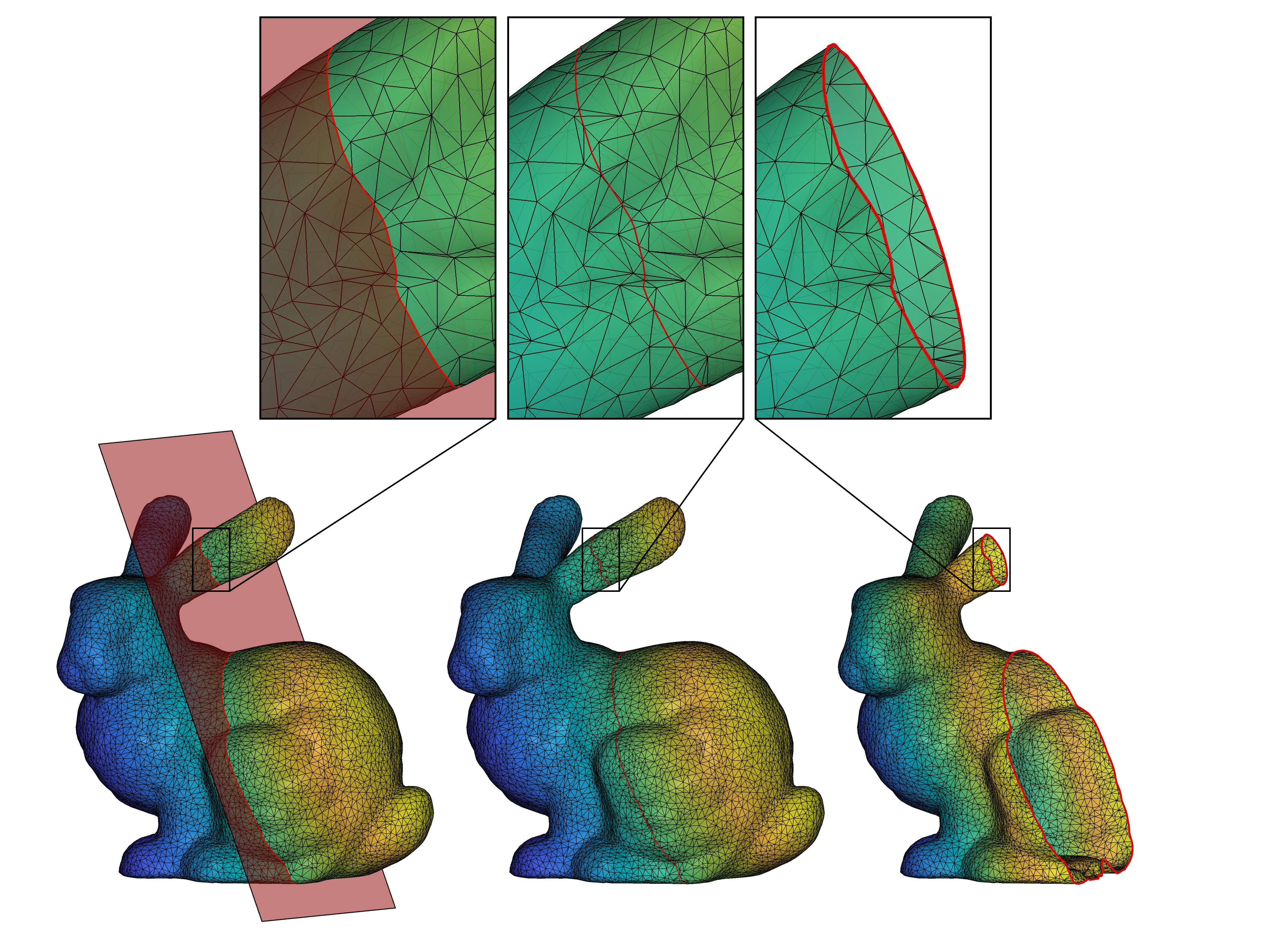
IsoCut.m: computes cut along level set of a scalar field and locally modifies connectivity of the mesh so it contains edges along the cut; enabling clean separation of mesh into disjoint components (i.e., surgery).
Q : What is a scalar field?
A : A function that maps spatial coordinates to a real value.
Q : What is a level set of a scalar field?
A : Suppose F(x) is a scalar field and x a position vector. A level set is a set of values of x that satisfy the equation F(x) - c = 0, where c is an isovalue of F. In function documentation, I use the terms level set, isocontour, and cut interchangeably.
Q : How do I evaluate a scalar field at the mesh vertices?
A : That depends on your application. Check out the demos for some examples. One common application would be slicing the mesh using a set of uniformly spaced cutting planes (see Demo 1). In that case, the scalar field is simply the equation of one of the cutting planes.
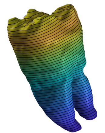
Extract and visualize planar contours at the intersection of mesh with k uniformly spaced cutting planes:
n=1; 				% index of principal axis specifying cutting plane normal
k=50;				% number of cuts
IsoCut_demo1(n,k)
Try calling IsoCut_demo1 with different values of n and k. Inspect code for more info.
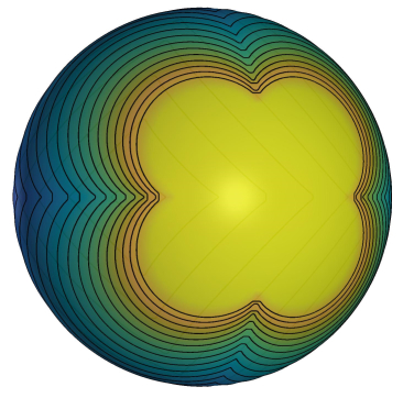
Examples of iso-contours on a unit sphere:
k=20;				% number of level sets
IsoCut_demo2(k)
Try calling IsoCut_demo2 different values of k; must be an integer between 1 and 20.
The previous demos showed how to extract the coordinates of the cuts/iso-contours. However, there may be applications that require insertion of the iso-contour polyline into the surface mesh. Doing so, for example, would allow us to perform 'surgery' on the surface so that the faces of the modified mesh to one side of the cut can be neatly separated from the faces on the other side to obtain two separate meshes. The cuts can be planar or non-planar, though they must be closed and non self-intersecting.
iv=0.6;				% iso-value
IsoCut_demo3(iv)
Try calling IsoCut_demo3 different values of iv; must be between 0.01 and 0.99
-
The function
OrderIsoContourVertsassumes that- computed level sets do not pass through saddle points of the input scalar field
- iso-contours extracted from closed surfaces are closed
- iso-contours extracted from open surfaces are either open or closed, but the end-points of open contours terminate at the surface boundary
-
At this time, the function
IsoCutworks only for closed iso-contours. The special case where the cut intersects with boundary edges is not yet supported. You do NOT have to worry about this exception if (a) the input surface mesh is closed, OR (b) the input surface mesh is open AND the cut does not intersect any of its boundary edges -
Level sets are computed using linear interpolation. If the field defined at the mesh vertices is produced by a nonlinear function (F), the iso-contours computed with
IsoContour.mwill be approximations of the corresponding level sets of F. In those cases, the only way to increase the accuracy of the extracted iso-contours is to linearly subdivide the mesh (prior to calculation of the scalar field at the vertices) until the error is below desired tolerance (e.g., see TriQuad.m from the S2-Sampling-Toolbox repo). If there is sufficient interest in an accurate extraction of iso-contours for nonlinear scalar fields, I can incorporate a zero-finding algorithm into the 'IsoContour' function, sometime in the future.
If you encounter any bugs/problems with this code you can e-mail me or repot the issue here.
MIT © 2021 Anton Semechko (a.semechko@gmail.com)


