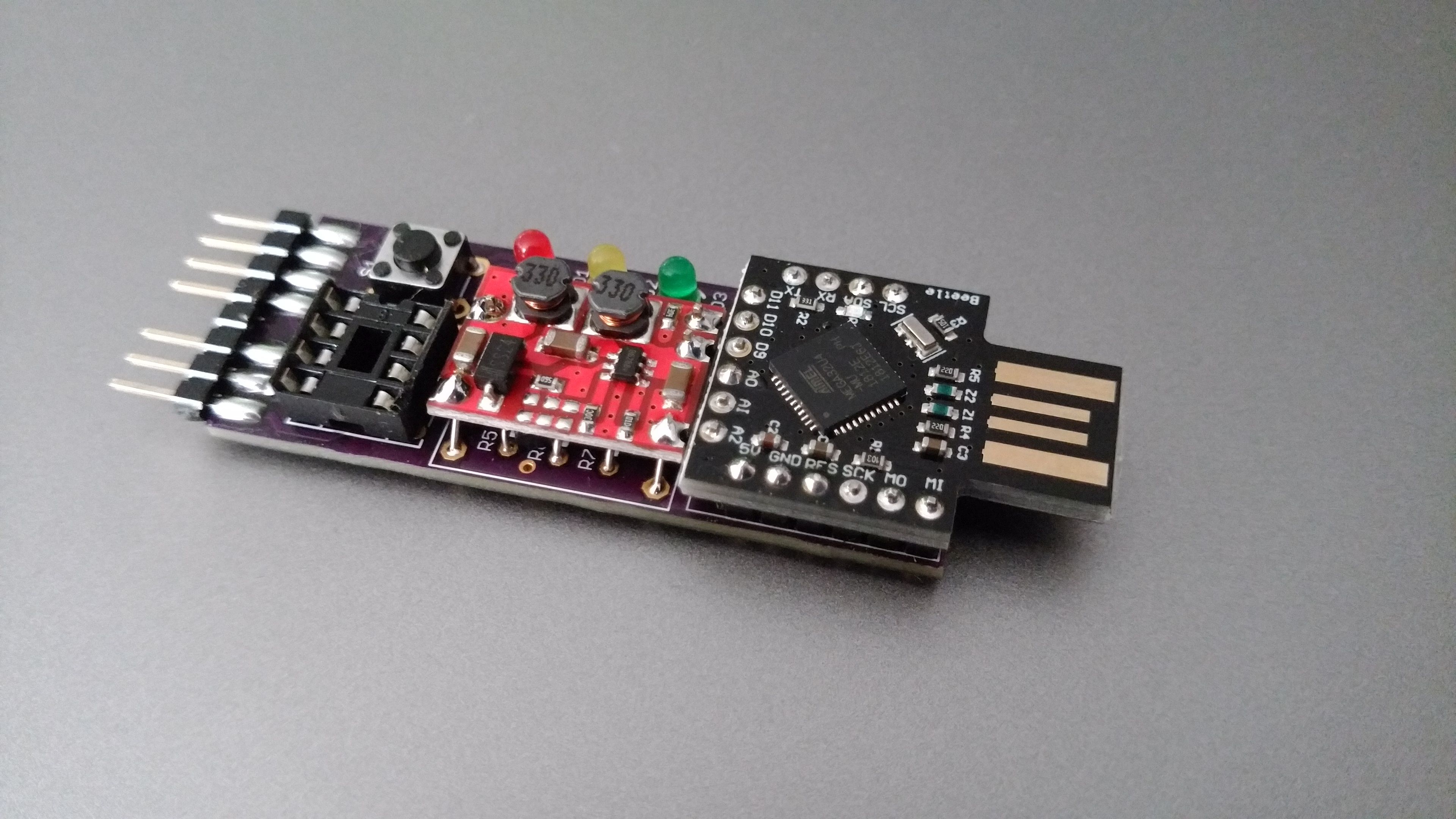
High voltage serial programmer for AVR Attiny devices
- Easy to make programmer using 12V DC-DC converter with enable and ATMEGA32U4 Beetle board.
- Programs AVR Attiny devices in high voltage mode to recover fuse settings and allow reset pin to be used as GPIO pin.
- Works with Arduino IDE / AVRdude.
- No hassle with Windows driver utilities. Uses built in windows 10 driver or Arduino IDE driver.
| Qty. | Discription |
|---|---|
| 1 | 12V DC-DC converter/booster module with enable |
| 1 | ATMEGA32U4 Beetle board without parts on PCB bottom + headers (No 3.3V pin and no extra GND pins on top row.) |
| 1 | 3 mm Red LED |
| 1 | 3 mm Yellow LED |
| 1 | 3 mm Green LED |
| 5 | 470 Ohm resistor (1/8 Watt) |
| 2 | 1K resistor (1/8 Watt) |
| 1 | PM48XP P-channel MOSFET SOT23 package (optional)* |
| 1 | 8 pin header (for programming connector) |
| 1 | 2 pin header (for DC-DC converter) |
| 3 | 1 pin header (for DC-DC converter) |
| 1 | 8 pin IC socket |
| 1 | 6x6mm tactile button |
*A MOSFET is recommended for a more powerful VCC. However if devices are only programmed using the IC socket or in low power circuits (<20mA), the MOSFET can be left out. In that case VCC is powered by a GPIO pin by shorting jumper J1. When using a MOSFET, Jumper J1 must be left open.
Revision 1.1 PCB can be ordered through OSH Park
Assemble parts with low height first (programming header, MOSFET at bottom, resistors IC socket, button, LEDs and modules as last). Check a parts aligment after soldering the first pin and when it's aligned properly solder remaining pins.
Before soldering the module headers, place headers with long end into main PCB and mount modules on top for easy aligment. Solder one pin of each header at top of module and check if headers are straight then solder remaining pins at top of the modules. Cut excess length of header pins at bottom of the main PCB and then solder them.
- Open hvsp.ino sketch by double clicking or open file with Arduino IDE
- Select Arduino Leonardo board from Tools menu.
- Select port from Tools menu.
- Upload sketch
Insert 8-pin DIP devices in to socket or wire-up device to programming header (check device datasheet for wiring). Upload a sketch using Arduino IDE or upload a hex file directly using AVRdude.
LED status:
- Red LED on: 12V VPP programming voltage on. Red LED off: Programming voltage off.
- Yellow LED on: 5V VCC on. Yellow LED off: 5V VCC off.
- Green LED on: Both programming and VCC are off. Green LED off: VPP and/or VCC on.
Button control:
Short press (< 500 ms): Toggle VCC on/off. long press (>= 500 ms): TO DO
select Arduino as ISP (ATmega32U4) as programmer from Tools menu
Use -carduino as programmer switch and specify serial port with -P switch