This utility converts an Altium .pcbdoc file to a Kicad .pcbnew file, optionally creating a library for the components found in the pcbdoc file.
The writing of this utility was inspired by the altium2kicad software which can be found here (https://github.com/thesourcerer8/altium2kicad) which is written in perl.
I've written mine in C# to hopefully provide a more complete convertor than altium2kicad. altium2kicad has provided much help in decyphering the ridiculous Altium file format. N.B. altium2kicad (or similar) will still be required to convert the schematic files. At the moment I don't intend doing the schematic conversion.
I wrote it in C# mainly to get genned up in C#. Purists may want to convert it to C++ in which case please feel free. Certain parts would probably be easier in C++.
To run this software type
USAGE
      ATOK [FLAGS] filename [2>errors.txt]

FLAGS:
      -e           to extract the subfiles of the pcbdoc (as altium2kicad)
      -l           to create a library of the components found in the .pcbdoc file

      filename     e.g. yourpcd.pcbdoc the file to convert
      2>errors.txt optionally redirect any run time errors into a text file
A directory called yourpcb-Kicad will be created and within it will be the converted file yourpcb.pcbnew along with a MODELS file
which contains any .step files found in the original document.
If -e is requested on the command line there will also be a directory called "Root Entry".
This contains a number of subdirectories called "Advanced Placer Options6", "Arcs6" etc.
These are the extracted subdocuments and typically contain a file called data.dat.
The format of the data.dat file varies from document to document, some are text files
some are binary some are a mixture, see the source code if you wish to
study the file contents.
If -l is requested there will be a subdirectory called yourpcb.pretty created within which will be a xxx.kicad_mod
file for all the different components found in the pcbdoc file.
There will be one file for all the 0603 models (say) found and ditto for all other components.
Some work will probably be required to make the models fit properly to KiCad specifications.
This utility has been tested on a limited number of PCB files which all tend to use certain
conventions for the mechanical layer usage.
For instance I've assumed that Mechanical Layer 1 is used for the board outline and any cutouts
within the board.
However the latest mod I've done is to get the board outline from the Board6 subdocument.
Any cutouts are defined by regions in the Regions6 subdocument which have the text ISBOARDCUTOUT=TRUE.
Thus obviating the outline to be defined by the mechanical 1 layer or whatever layer has beens used.
The extracted 3D models (if any) in the MODELS directory have their checksum included in the filenames. This is to guard against 3d models having the same name but different contents. This caused the loss of many hours where I had two models with same name but different content e.g. different orientations.
Shape based component models have not been imlemented but if anyone is up to it please feel free
to convert the shape based information into .step type 3D models.
Only a subset of dimensions has been implemented.
The yourpcb.pcbdoc file is a "Microsoft Composite Document File" and is accessed using the openmcdf library found here (https://github.com/ironfede/openmcdf).
Step 3d model files found in the Models6 subdocument are unzipped using Ionic.Zlib.dll.
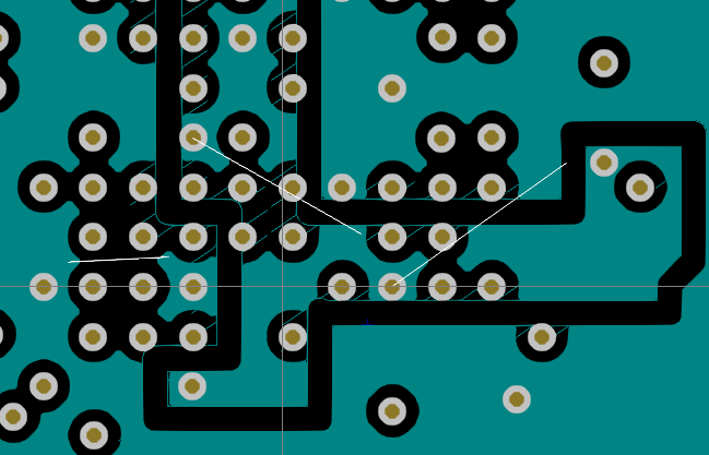
Of problems with the current PCBNew(5.1.2) the following picture shows why the inner layers of vias should be the size of via holes.
On the original pcb (Example1.PcbDoc) the 1.5V inner plane is able to spread between the vias. However under Kicad there are breaks in the copper fill.
On some boards when the 3D view is requested you may get a dialogue saying "Can't determine board outline".
This is caused by some tracks being on the Edge.Cuts layer coincident with the board outline.
These can be simply deleted by hand to remove this "error".
I've added code to reject any tracks or arcs which match any that exist on the Edge.Cuts layer already.
Please have a play on some of your own boards and feed back any anomolies you may find and at some point I'll try to remedy them.
Alternately fix them yourselves and offer up the fixes to be merged in.
Thanks and have fun.
