The wiki Documentation is here in French
Shield:
This work is licensed under a Creative Commons Attribution-NonCommercial-ShareAlike 4.0 International License.

Before connecting the photovoltaic control board to the electrical grid, ensure compliance with local electrical safety standards:
- Use properly insulated cables to avoid short circuits.
- Install protective devices, such as circuit breakers, to prevent overloads and short circuits.
- If unsure, seek the assistance of a qualified professional for installation.
- Always use Dallas probes to monitor temperatures.
Welcome to the official documentation of Cyril's photovoltaic router (C_lyric). This comprehensive resource has been designed to help you install your Photovoltaic router
It's the opensource Pv router from the French association APPER, the board is open source,
but you can order it directly from the association and the association being recognized as being of general interest in view of French taxes, it generates a tax credit for French individuals. (60%)
I do not receive any euros from the sale of the cards and all the work of developing the cards and the software is purely voluntary. But a little encouragement is always nice.

The DIN format card: is available to order on Helloassos (the TTGO is not provided and the appearance of the card may vary a little) and it is supplied with the DIN support.
For European countries, shipping costs are included in the price.
The router take the measurements and controls the remote or local dimmers.
Simpler than a long speech:
For practical reasons, programming the router is done directly from a web page, from a compatible browser (Chrome or Edge) go to the page: https://ota.apper-solaire.org/ota.php
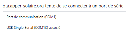
In the window that opens, select the serial port to which the TTGO is connected
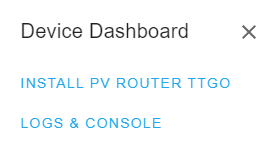
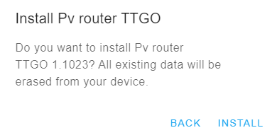
Select “INSTALL PV ROUTER TTGO”
Validate the installation message.
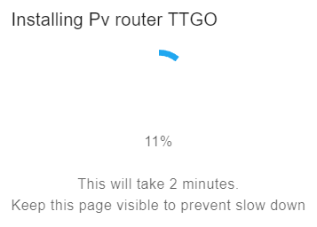
The program is uploaded:
There are a simple methods to connect to wifi: ( or by AP mode )
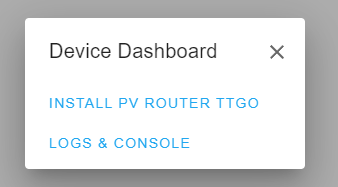
Once programming is done, choose “Log & console”
From there you can use a series of commands to configure your wifi: ( put your password first )
pass your_ssid_pass
ssid your_ssid

reboot
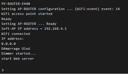
Vous pourrez alors voir en direct si vos informations wifi sont bonnes

You will be able to consult IP and the wifi power level directly on the TTGo display (top right)
- in yellow below -64dBm
- in orange below -70dBm
- in red below -80dBm
The Photovoltaic Router is responsible for analyzing the direction of the current at the electric meter using the probe (SCT013) placed on the Phase wire.
If the current is positive, the house consumes current from the electrical network.
If the current is negative, the installed solar panels provide more energy than the house currently consumes.
The goal of the router is therefore to increase the power of a resistive remote load to compensate for this overproduction.
In general, this load is an energy or heat storage zone which will be necessary at a later time (hot water, mass heating, battery, EV, etc.)
We therefore maximize the self-consumption of our photovoltaic installation, and we reduce its impact on the electricity network. (and associated future costs)
Once the code has been uploaded via the website and the entire router assembled, it is possible to connect with your web browser to the IP which is displayed on the display of your PV router.
You can therefore consult the information reported by the PV router.
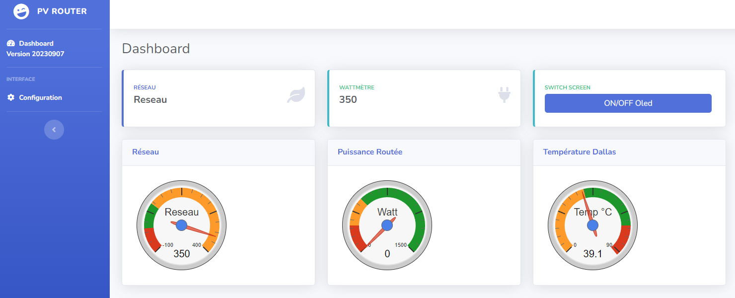
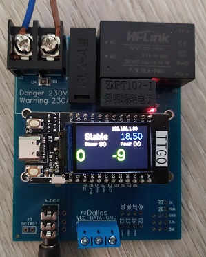
On this interface you will find a gauge with the power requested from the network (Sigma, in W), the power requested from the dimmers (in %) and the temperature (in °C) reported by the probe of the 1st dimmer if existing (or probe present locally).
For the power requested from the network there are 3 states which are configurable:
- Stable: the PV router has stabilized consumption.
- Injection: The PV router will gradually increase the load to stabilize consumption
- Grid: The Pv router will reduce the load to limit the needs of the house.
On this interface, there is also an “ON/OFF Oled” button which is responsible for turning the Oled screen of the TTGO T-Display on or off.
This can just be a delay on or off until the next button press.
(ON/OFF or timer)
This delay is configurable in the web configuration interface.
This button is also remote on the PV router, it is the right button of the TTGO

On the base page (Dashboard), there is a “Configuration” link which points to the /config.html page
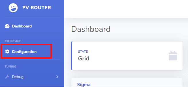
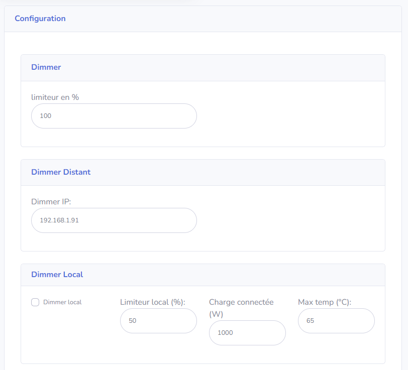
This page allows you to configure all the features of the router.
Before connecting the photovoltaic control board to the electrical grid, ensure compliance with local electrical safety standards:
- Use properly insulated cables to avoid short circuits.
- Install protective devices, such as circuit breakers, to prevent overloads and short circuits.
- If unsure, seek the assistance of a qualified professional for installation.
- Always use Dallas probes to monitor temperatures.
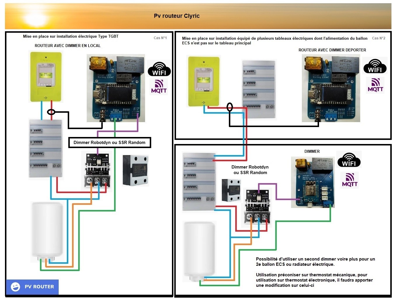
Diagram made by Titi.

The card has its own protection against overloads (.15A glass fuse or automatic), but it is recommended to place it behind a circuit breaker (2A)
As part of the installation of the Router card without a dimmer installed, all you have to do is install the card in the electrical panel and connect the SCT013 probe to the jack provided for this purpose.
The probe must be at the output phase of your electric meter (between the Linky and the panel).
As part of the installation of the Router card with dimmer,
In addition to installing the SCT013 probe as previously, you must connect the Dimmer Robotdyn to the location provided on the card.
The ball will connect to it.
A Dallas 18B20 probe is strongly recommended to avoid any overheating of the tank.
It is also strongly recommended to connect the Robotdyn power supply downstream of the tank electronics to have double temperature security. This allows the power to be cut off in the event of a temperature rise.
The fault of this type of configuration is that in return it is no longer possible to exceed the max setpoint of the tank set on the original heat tank card.
The regulation of the tank by the dimmers (SSR or Robotdyn) is done by chopping the current, this causes disturbances on the electrical network. It is therefore very strongly recommended on soapstone balloons to only use one of the resistors present, which is more than sufficient. The regulation will be finer and will cause fewer disturbances.
The values announced in terms of admissible amperage on the dimmers are fanciful. Connecting too high a load can also lead to excessive heating of the regulation part of the dimmer (tryac) and no longer be controllable by the control part. It is therefore advisable either to limit the power connected to it or to ventilate the radiator to increase heat dissipation. (the more resistant SSRs are a little less impacted than the Robotdyn dimmers)
This is why I recommend taking the largest Robotdyn dimmer (20A) or SSR Random 40A minimum.
The router is compatible with MQTT, HA, Jeedom and domoticz.
It can also interface with an external power calculation source such as Shelly EM