Team Members: Evan Chien, Miaoding Dai, Ana Pervan, William Wang, Michael Wiznitzer
Northwestern University ME 495: Embedded Systems in Robotics (Fall 2017)
The goal of this project is for Sawyer to navigate a ball through a maze using vision feedback.
A Sawyer gripper mount, spacers, and a maze base were designed using OnShape. These were laser cut and glued together so that they could be mounted on the Sawyer, and any maze with the same corner mounting holes could be attached or removed using screws.
Next, a maze was designed, cut, and painted blue. The maze base was painted black, so that the camera could clearly differentiate between the walls and the background. Once the maze was mounted, a white ball was placed in the starting position and a green sticker was placed at the desired ending position.
Sawyer's head camera's resolution would not work for this project, so a separate tripod and a 720p webcam were used to record the maze and ball. A node identified the blue outline of the maze by transforming the corners that it detected onto a 30cm square (the dimensions of the maze were known ahead of time). So no matter the orientation of the maze, a top-down view could always be extrapolated. Next, the position of the rest of the blue walls in the maze were identified, as well as the position of the white ball and the green "final position" sticker. This information was all passed along to the Path Planning node.
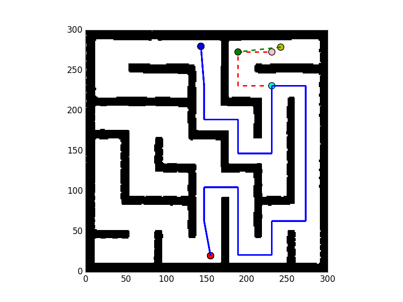
A grid-based planning algorithm (using a modified version of the RRT approach) was used to solve the maze. The maze was divided into a 7x7 grid, so that the sampling process moved very quickly. A global plan, from the initial ball location to the desired final location at the green sticker, was constructed and then a local plan, from the current position to the next determined grid point, was sent to the Robot Control node. The local path was updated with new ball position information at approximately 30Hz.
An example path planning sequence is shown in the picture below the following description:
Global Path:
- Red Point = Starting Configuration
- Blue Point = Ending Configuration
- Blue Solid Line = Global Path
Local Path:
- Pink Point = Closest node to current ball position
- Cyan Point = Closest global path node to current ball position
- Red Dashed Line = Local Path to closest global path node
- Yellow Point = Current ball position
- Green Point = Next determined point to travel to on local path
- Green Dashed Line = Commanded Path from current ball position to next determined point. This distance vector is what is sent over to the Robot control node.

Sawyer was programmed to begin at the same initial position each time, holding the maze level and low, so that it was in view of the camera. After moving to the initial position, only two joints were used (joint 4 and joint 5) to move the ball in the positive and negative x and y directions. The error between the current ball position and the next desired position (from the local path) was detected, and then two PID controllers (one for joint position and one for joint velocity) were used to get the ball to the next point in the local path. The final values for the PID controllers were:
- joint position: kp = 0.01, ki = 0.005, kd = 0.0.
- joint velocity: kp = 0.001, ki = 0.0, kd = 0.0.
These values were found experimentally, while testing Sawyer with the ball and maze. Having both controllers allowed Sawyer to swing the ball into turns where there was no "backboard" (a wall for the ball to stop at before turning). Also, if the ball ever got stuck, the ki term got larger and larger so that Sawyer kept rotating the maze until the ball moved.
Subscribed Topic: /usb_cam/image_raw
Published Topic: /ball_pos
Services: /maze_start /maze_dest
Subscribed Topic: /ball_pos
Published Topic: /testing_error
Services: /maze_start /maze_dest
Subscribed Topics:
/testing_error
/robot/joint_states
A video of Sawyer solving the maze can be found here.
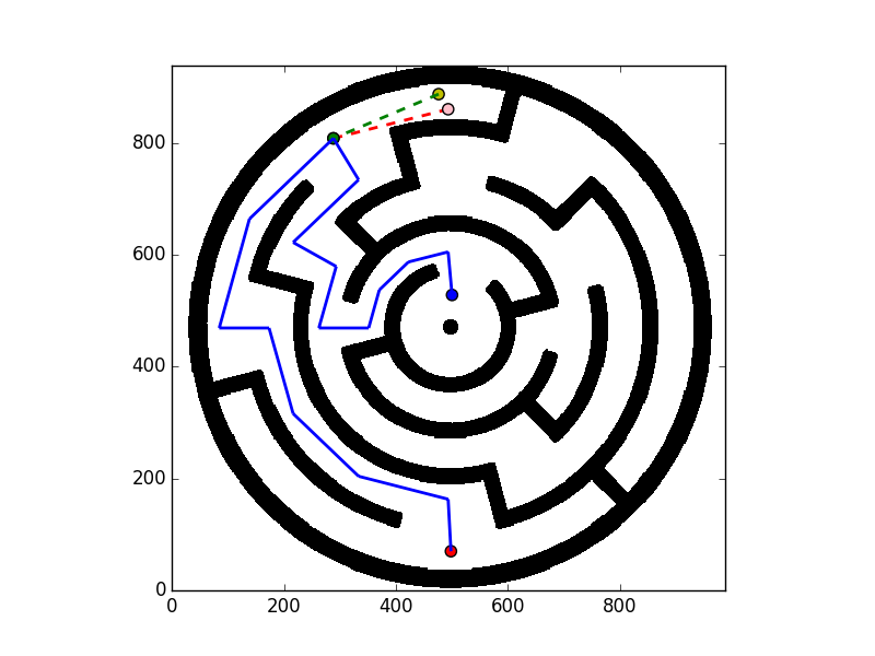
We had already started building a new, circular maze and revising the path planning algorithm to use a grid with polar coordinates, but in the end we did not have time to alter the computer vision code to identify the circular shape or to experiment the dynamics of the circular maze. But solving the square maze for different starting and ending points lead to a lot of different possible maze paths -- almost as if we had made many mazes.
We could also further improve our controller so that Sawyer would more reliably make the difficult turns on the first try. We could do this by experimenting more with our PID values, or changing controllers entirely (for example, to an LQR controller).
For a sneak peak into an example path planning sequence for the circular maze, see the below picture.
