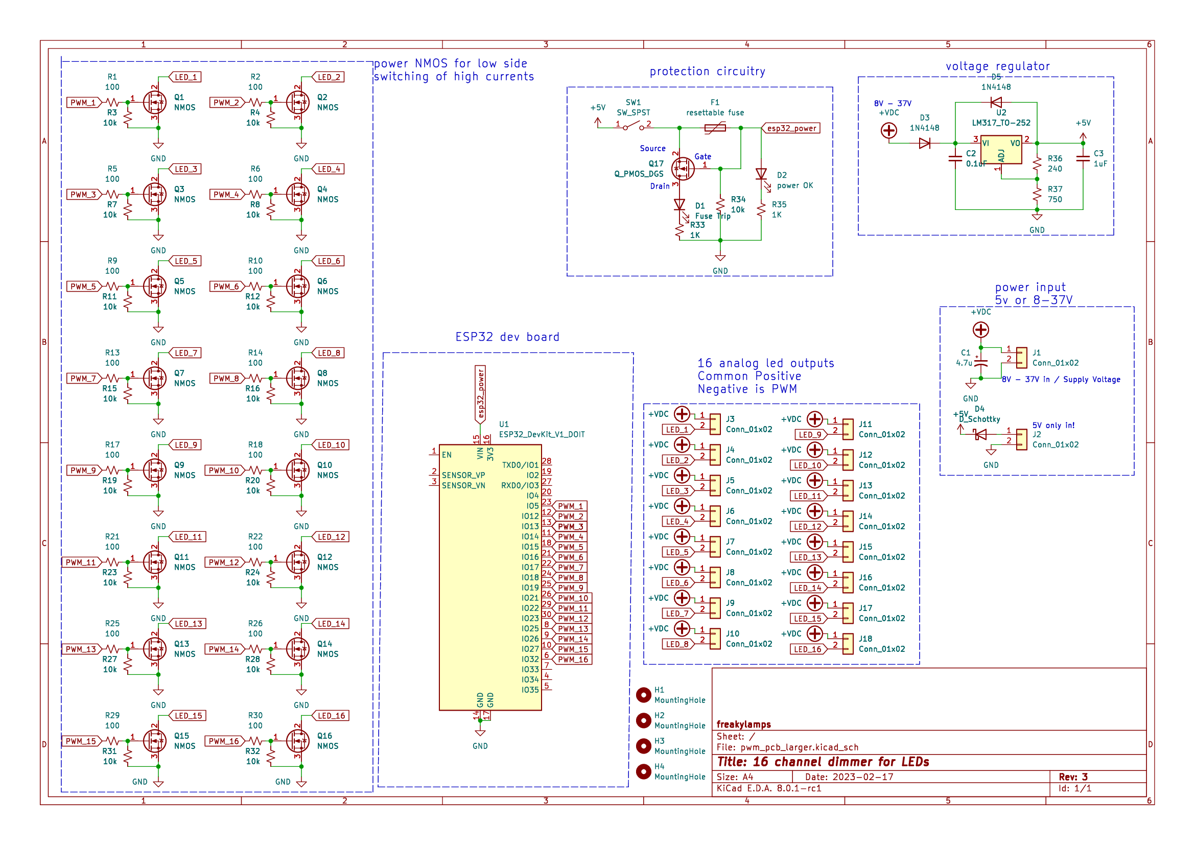
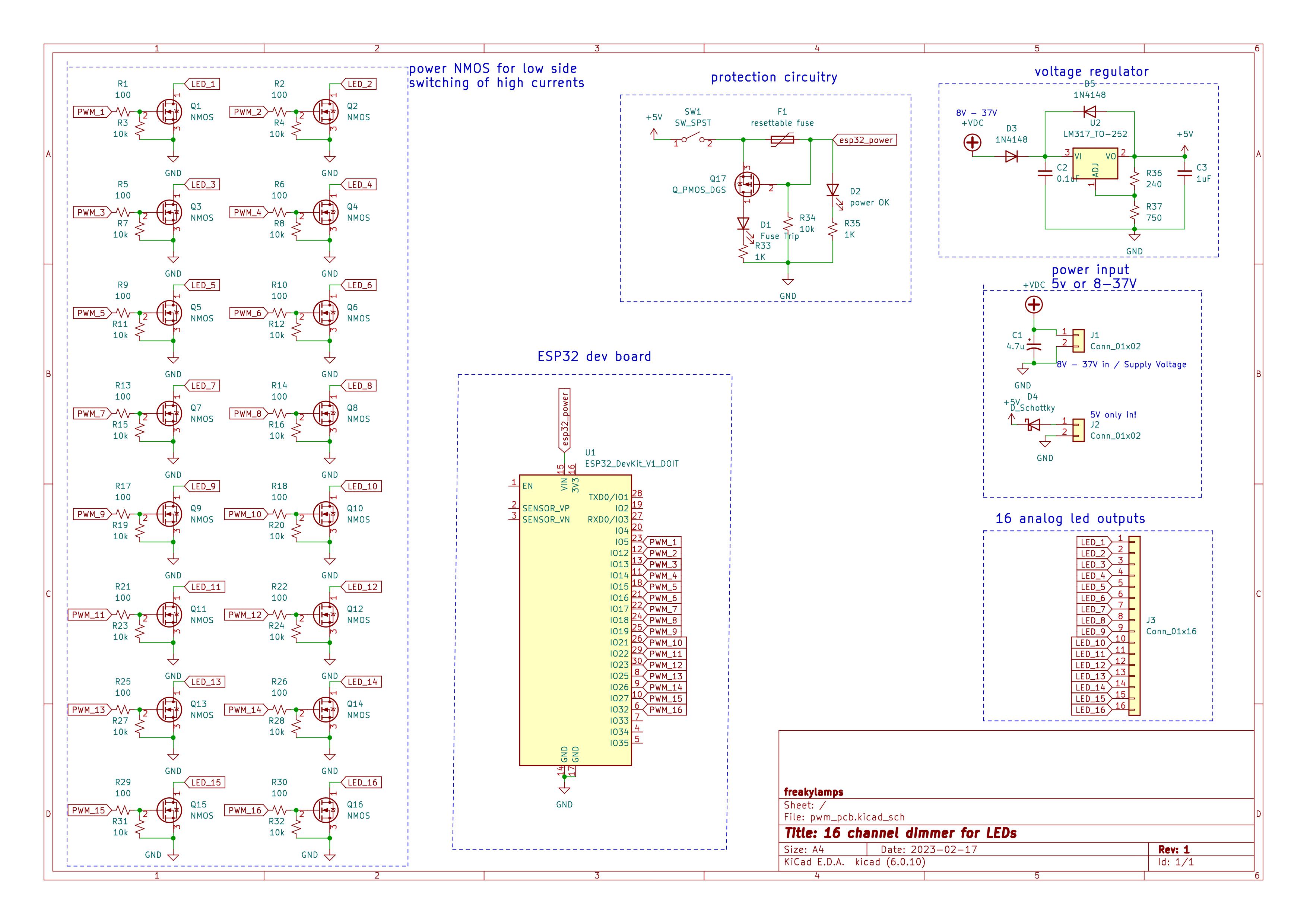
this repo contains the files for a 16 channel pcb to dim LEDS.
I designed this board originally for my friend Eddie Farr for an led sculpture he is working on. I've also wanted something like this for a while to dim analog LED strips easily via WLED or ArtNet, or just plain old locally from a microcontroller.
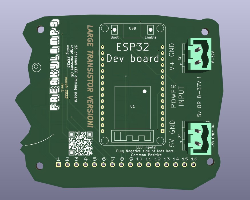
It is designed to take in voltages from 5 to 37 Volts to power the ESP32. That way you can use this with 12 or 24 volt LEDs and dont have to deal with an extra 5V power supply to power the esp32.
There are two separate places to put power in. EITHER plug 5V into the 5V side, or plug 7 - 37V into the other side.
LED1 = GPIO 5
LED2 = GPIO 12
LED3 = GPIO 13
LED4 = GPIO 14
LED5 = GPIO 15
LED6 = GPIO 16
LED7 = GPIO 17
LED8 = GPIO 18
LED9 = GPIO 19
LED10 = GPIO 21
LED11 = GPIO 22
LED12 = GPIO 23
LED13 = GPIO 25
LED14 = GPIO 26
LED15 = GPIO 27
LED16 = GPIO 32
Rev. 3 - pcb with larger transistors and larger connectors:
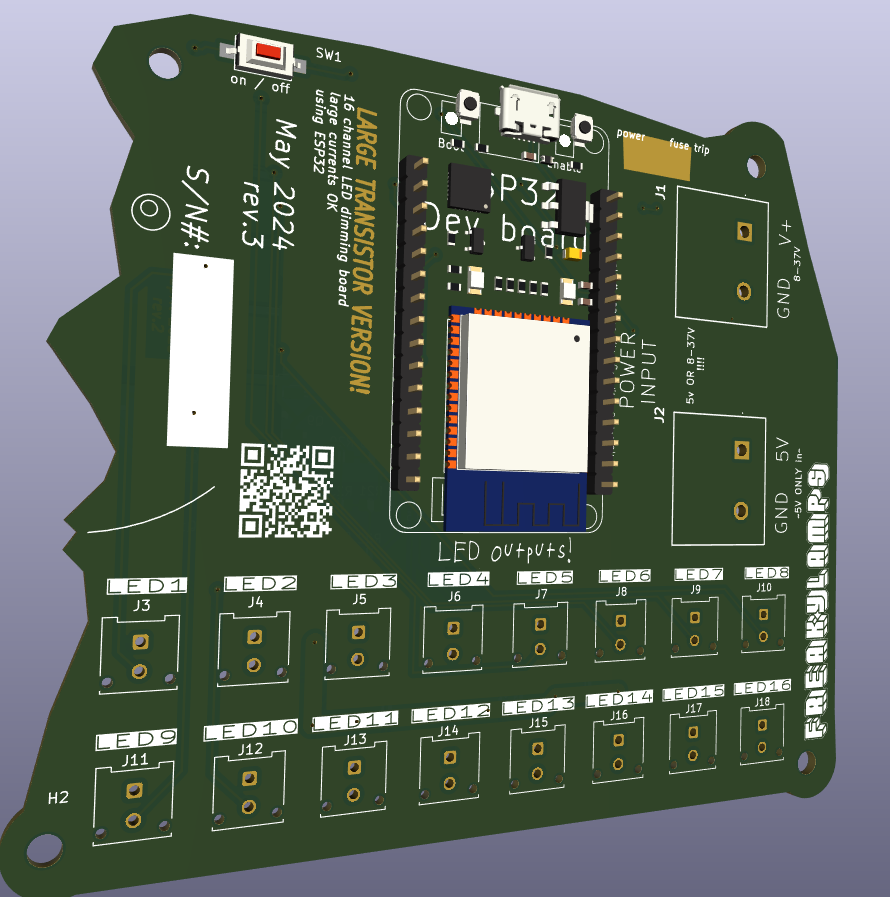
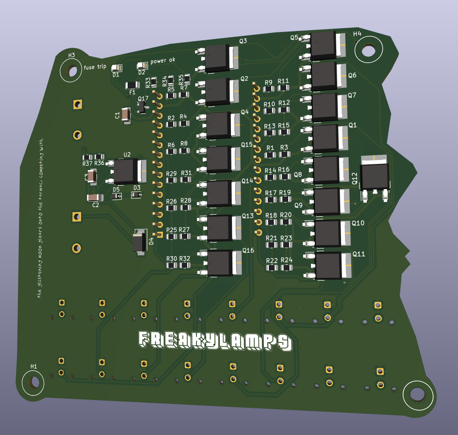 Rev. 1 - pcb with larger transistors:
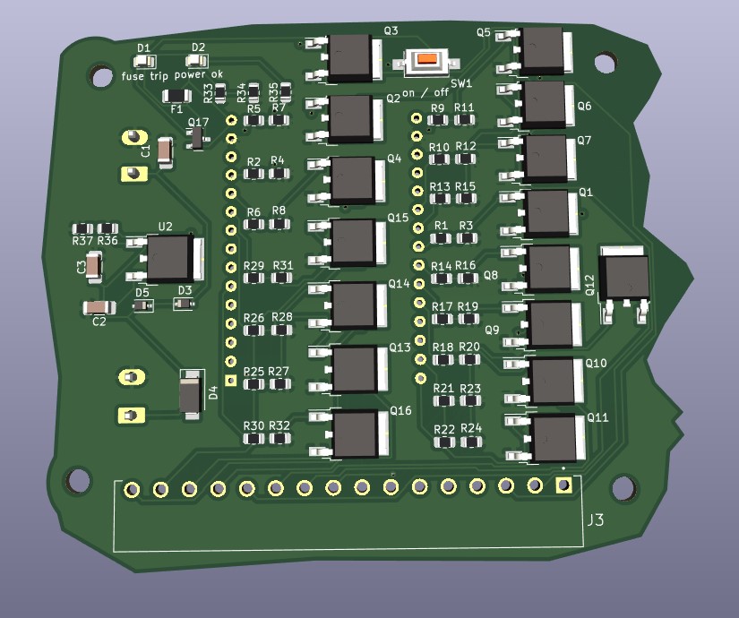
Rev. 1 - pcb with smaller transistors:
- On version 1.3 we are trying out some Molex Microfit connectors
- Crimping tool - Engineer PA09
-
Mouser Cart for QTY 5 REV2 boards - this is parts not included with the JLCPCB assembly.
-
Recommended Generic Crimper for Molex Microfit Connectors
-
using ESP-WROOM-32 dev board. 2.05" x 1.18" like the kind found here
-
Both pcbs mount with M3 screws
-
board has two places for power. one for 5V and one for 8V - 40V. The two connectors MSTBV/MSTBA Phoenix Type, 5.08 pitch.
- straight receptacle/header: 1747993 (green) or 1836561 (orange) or 1740893 (black)
- right angle receptacle/header: 1736036 (green) or 1702878 (white) or 1876848 (orange)
- terminal block plug: Wurth 691351500002 or Kobiconn 158-P022ESDVP-E or Amphenol TJ0251530000G
- Enclosure mounts with #8 wood screws
- the larger board uses 3.81mm pitch connector for led outputs
- 16 channel plug - pluggable screw terminal block - TBP02P1-381-16BE
- screw terminal receptacle/header TBP02R1-381-16BE
- smaller board uses 2.54mm connector for led outputs
Any advise for common problems or issues.
- 1.0
- Initial Release - March 15, 2023
- 1.1
- new design with larger TO-252 package for NMOS - March 20, 2023
- 1.2 - april 5, 2023
- v2 of smaller board. v1 had NMOS pinout wrong
- Rev 3 - May 22, 2024
- large boards are now larger, using MicroFit connectors for the led outputs, terminal block for PSU inputs
- switch is on front now
- Q17 had pinout wrong
This project is licensed under the [NAME HERE] License - see the LICENSE.md file for details
Inspiration comes from quinLED's analog boards
