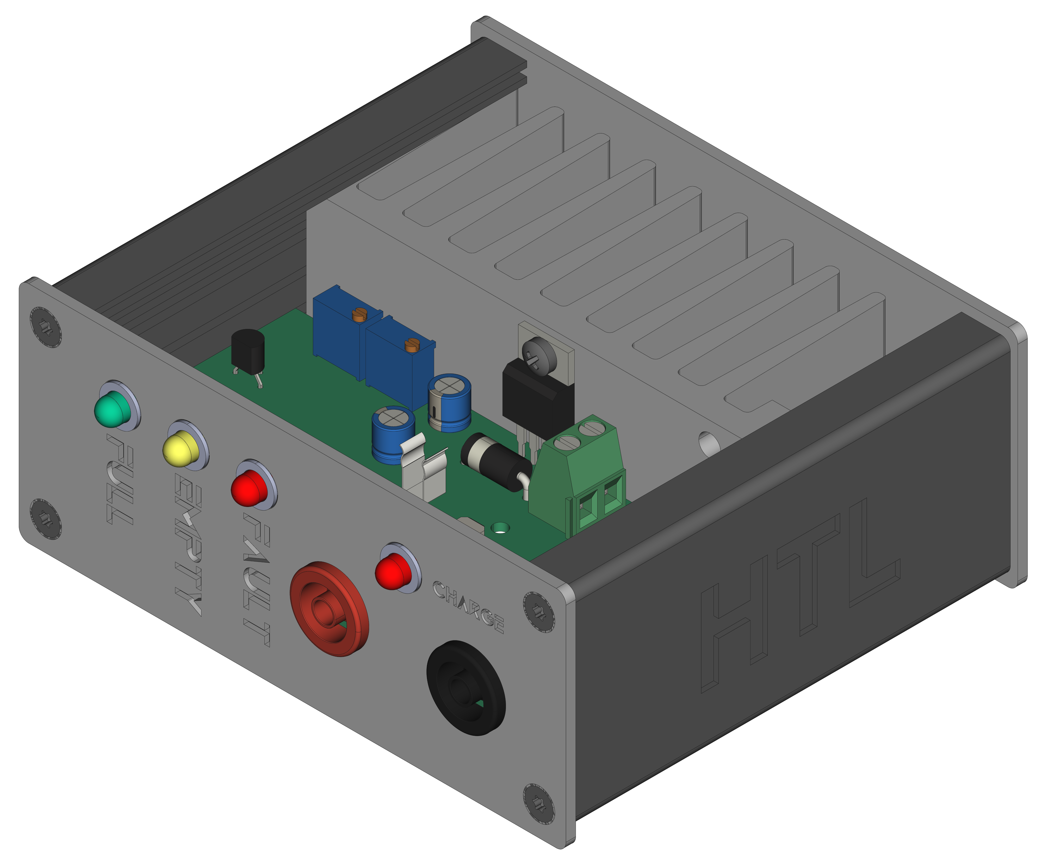
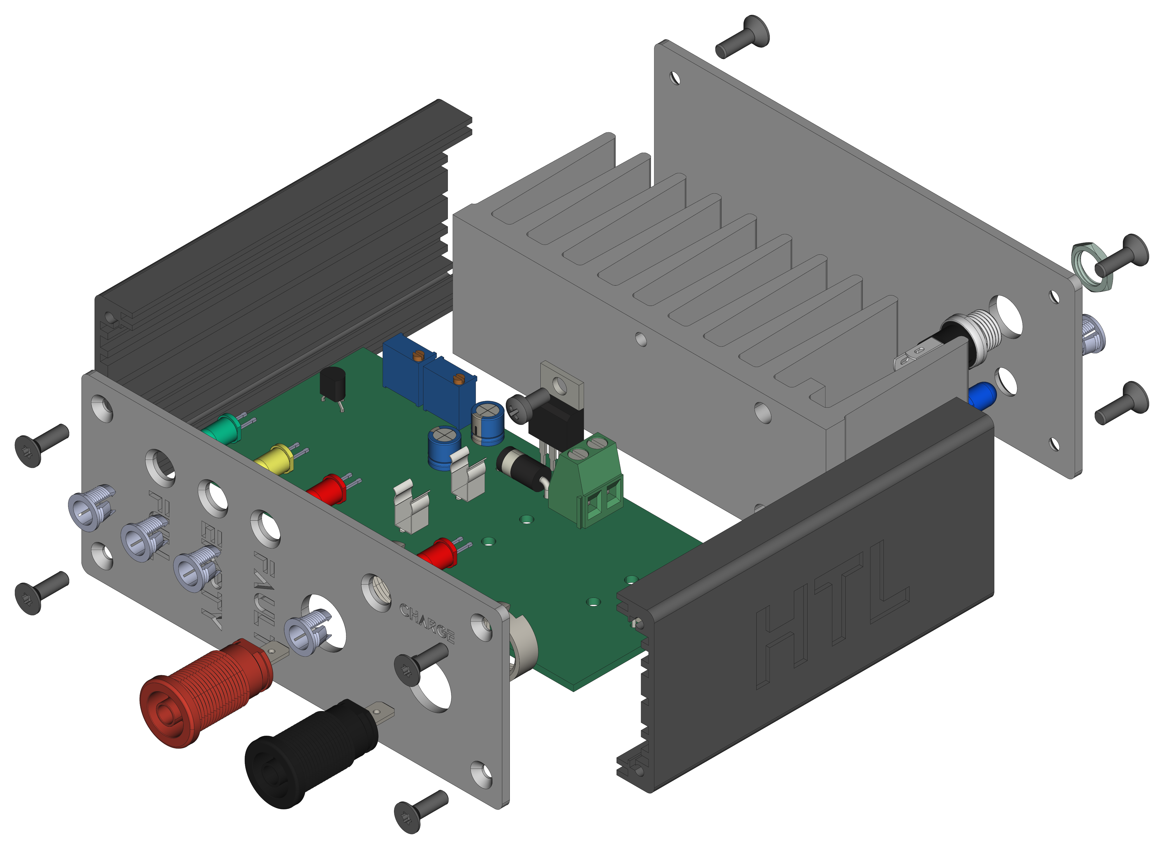
The BLR project is based on a pcb with a positive voltage regulator for battery charging (PB137). It can be used to charge lead-batteries with a voltage of 12V and observe the status of a battery during use.
| Experience | Level |
|---|---|
| Soldering | |
| Mechanical |
| Type | File | Description |
|---|---|---|
| Simulation | asc | LTSpice Simulation |
| Lochmaster | lm4 | Stripe grid circuit board |
| Schematic | pdf / cadlab | Schematic files |
| Board | pdf / cadlab | Board file |
| Drill | Drill file | |
| Gerber | zip / tar | Gerber/Drill files |
| Housing, PCB | zip / tar | Housing and PCB (STEP) files |
There are two parts of the hardware. The pcb and the housing of the BLR. The pcb is created with KiCAD and the housing with FreeCAD. All files are built with github actions so that they are ready for a production environment. The housing is printed with a 3D-printer (Dremel 3D40).
The circuit board is populated on both sides (Top, Bottom). The best way for soldering is within a vapor phase soldering system.
The housing has a tolerance of 0.2mm on each side of the case. So the pcb should fit perfectly in the housing. The tolerance can be modified with FreeCAD in the Parameter Spreadsheet.
To setup the BLR the reference voltages of TP1, TP2, TP3 and TP4 needs to be adjusted.
| Point | Voltage | UIn |
|---|---|---|
TP1 |
~2V5 | ~8V |
TP2 |
~2V5 | - |
TP3 |
~2V5 | ~13V |
TP4 needs to be adjusted manually with an Ampermeter. If the current is >
100 mAthe charging LED (J8) should be on. This behaviour can be adjusted throughRV3.
| Type | Link | Description |
|---|---|---|
| PB137 | Positive voltage regulator for battery charging datasheet | |
| TL431 | Precision voltage reference | |
| LM358 | Dual operational amplifier | |
| Battery | web | Lead battery with 12V |
R. GAECHTER


