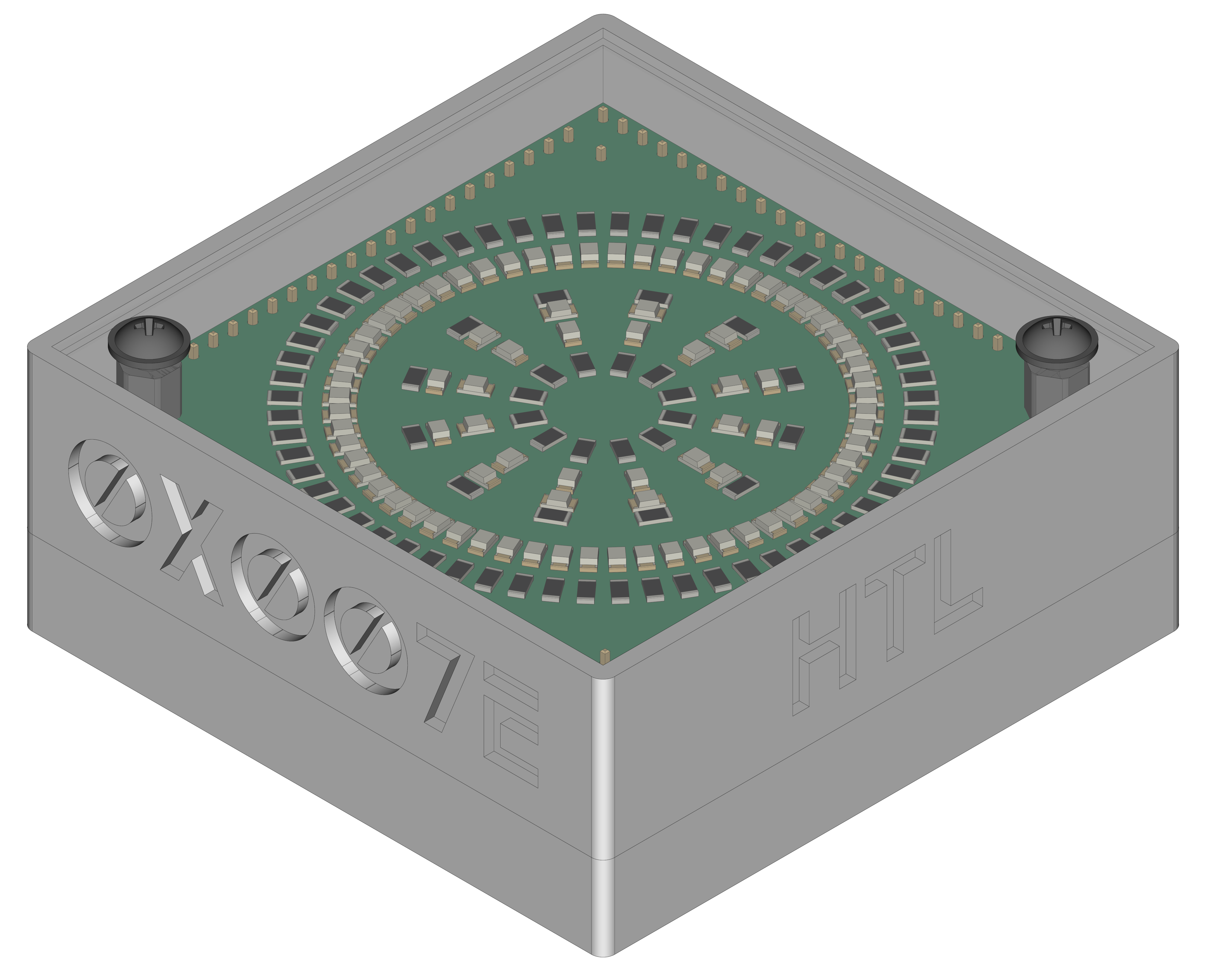
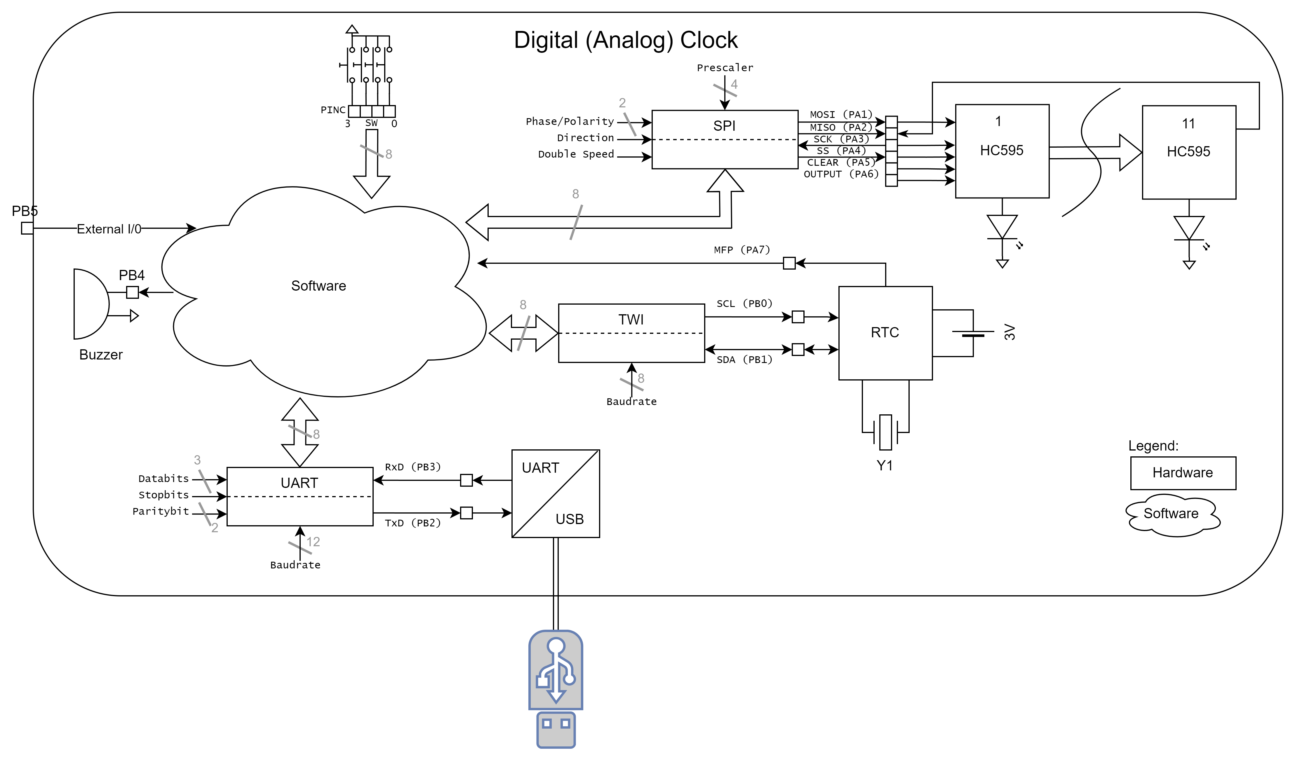
The DIU project is based on a pcb with an ATtiny1606 a RTC MCP7940 a USB/UART bridge FT232RL and a set of 74HC595 shift register. It can be used to display time and date on 84 LEDs that are mounted in 3 circles to the top pcb. The clock itself can be setup over UART and a terminal software (e.g. TeraTerm).
| Experience | Level |
|---|---|
| Soldering | |
| Mechanical | |
| Software |
| Type | File | Description |
|---|---|---|
| Schematic | pdf / cadlab | Schematic files |
| Board | pdf / cadlab | Board file |
| Drill | Drill file | |
| Gerber | zip / tar | Gerber/Drill files |
| Housing, PCB | zip / tar | Housing and PCB (STEP) files |
| Firmware | zip / tar | Firmware for ATtiny1606 |
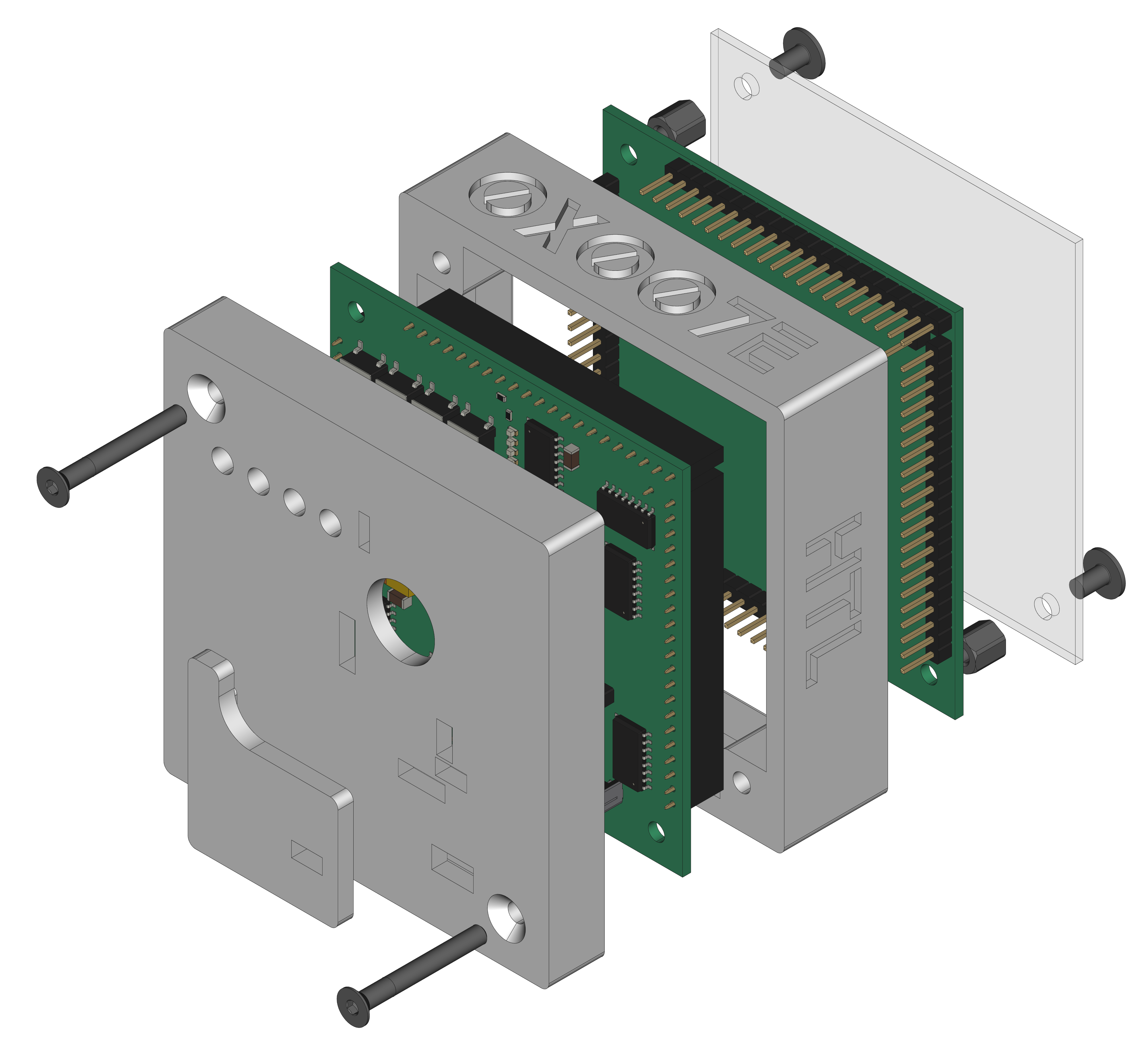
There are two parts of the hardware. The pcb and the housing of the DIU. The pcb is created with KiCAD and the housing with FreeCAD. The software is programmed with Microchip (Atmel) Studio. All files are built with github actions so that they are ready for a production environment. The housing is printed with a 3D-printer (Dremel 3D40).
The circuit board is populated on both sides (Top, Bottom). The best way for soldering the SMD components is within a vapor phase soldering system and for the THT components with a standard soldering system. After placing and soldering the top parts, the board has to be cut off in the middle (white edge).
The housing has a tolerance of 0.2mm on each side of the case. So the pcb should fit perfectly in the housing. The tolerance can be modified with FreeCAD in the Parameter Spreadsheet. The corners of the circuit board need to be sanded a little.
The DIU can be powerd with 5V from USB or an external source through connector J1. Over UPDI (J3) the DIU can be programmed with avr-dude or an Microchip (Atmel) ICE adapter. To setup the DIU it can be connected over USB to a computer and configured with a terminal (e.g. TeraTerm) software. The firmware for the clock can be downloaded from the download section.
| Register | Value |
|---|---|
WDTCFG |
0x00 |
BODCFG |
0x00 |
OSCCFG |
0x02 |
TCD0CFG |
0x00 |
SYSCFG0 |
0xF5 |
SYSCFG1 |
0x00 |
APPEND |
0x00 |
BOOTEND |
0x00 |
To setup
RESET(PA0) it is necessary to change theSYSCFG0-FUSE of theATtiny1606. WARNING: To reset thePA0pin toUPDImode a12Vimpulse is necessary to program the FUSES again.
The firmware of the DIU project can be downloaded and modified with Microchip Studio. The software can be found in the ./firmware directory and is splitted into different libraries. They can be found in the ./firmware/lib` folder. Feel free to modify the firmware to your own needings.
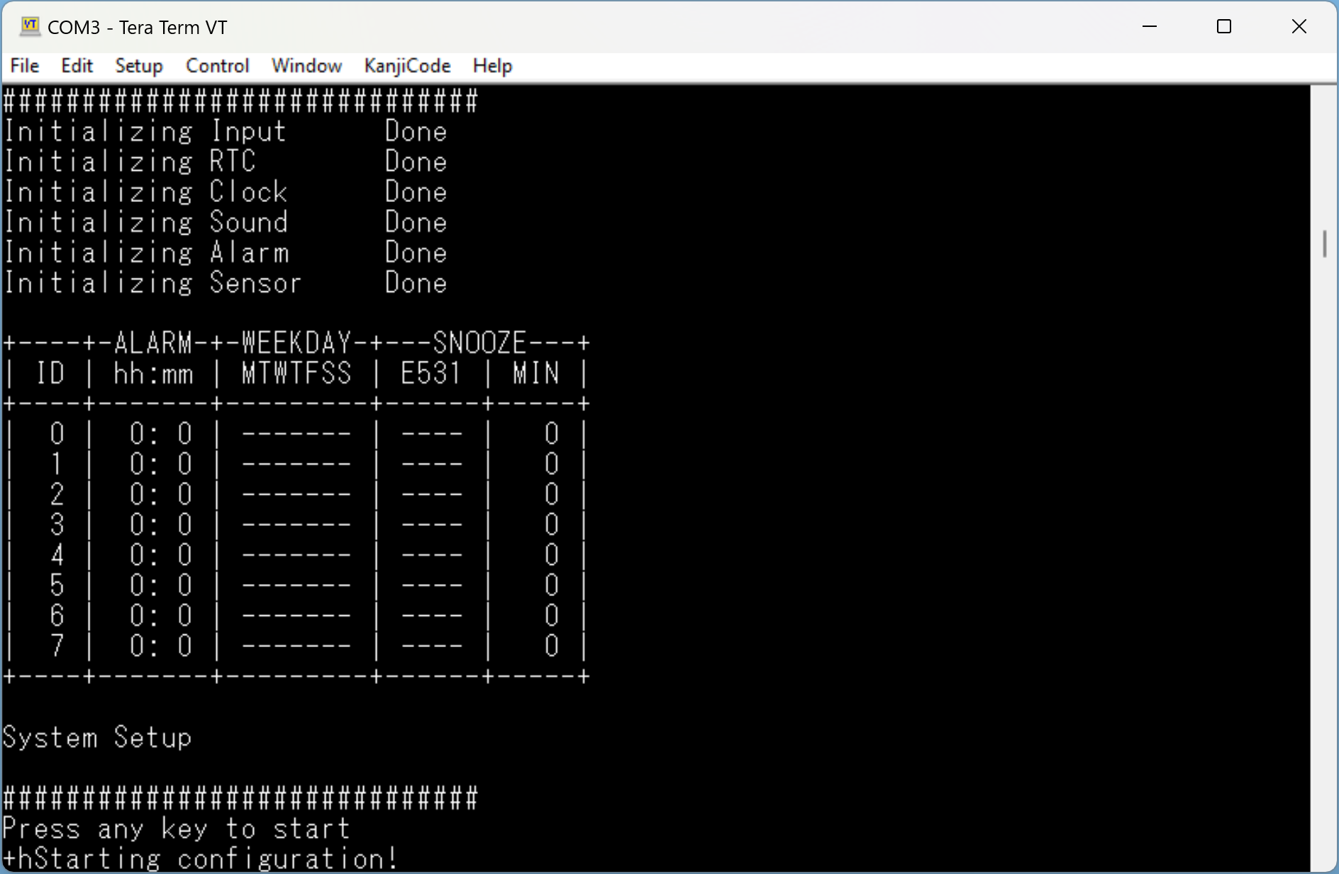
To configure the DIU through UART (USB/UART bridge) a connection over USB to a computer and a terminal software (e.g. Teraterm is necessary. To start the setup the following settings need to be configured in the terminal. Then hit a key during init process in the terminal.
| Name | Value |
|---|---|
| PORT | COM? |
| BAUD | 9600 |
| DATABITS | 8 |
| PARITY | NONE |
| STOPBITS | 1 |
| FLOWCTRL | NONE |
# +--------------------------------------------------+
# |       ~------------------+                       |      +---------------------+
# |      ~  ATTINY 1606      |                       |      |                     |
# |     ~                  +-+-+                     |      | +-----------------+ |
# |    ~               VCC | 1 |          +----------+      | | TeraTerm        | |
# |      ~             PB0 | 2 |          |   U  +---+---+  | | ~~~~~~~~        | |
# |        ~           PB1 | 3 |          |   S  |  USB  |--+ | ~~~~~           | |
# |         ~    (TxD) PB2 | 4 +-----+    |   B  +---+---+  | | ~~~~~~~~~~~~    | |
# |        ~     (RxD) PB3 | 5 +--+  |    |   /      |      | |                 | |
# |       ~            GND | 6 |  |  |    |   U      |      | +-----------------+ |
# |     ~                  +-+-+  |  |    |   A      |      |                     |
# |    ~~~~~-----------------+    |  |  +-+-+ R      |      | Computer            |
# |                               |  +--+TxD| T      |      |                     |
# |  DDD   IIIIII UU  UU          +-----+RxD| +------+      +---------------------+
# |  D  D    II   UU  UU                +-+-+ |5V/3V3|
# |  D  D    II   UU  UU                  +----+-----+
# |  DDD   IIIIII  UUUU                              |
# +--------------------------------------------------+To enter into the configuration mode it is necessary to press a key during startup.
The configuration starts and a menu to setup the DIU appears.
# +------------------------------------------------+
# | System Configuration                           |
# +------------------------------------------------+
# | [1] Time and Date                              |
# | [2] Alarm                                      |
# | [3] Alarm Tone                                 |
# | [4] LED Intensity                              |
# | [5] Oscillator                                 |
# | [d] Discharge changes                          |
# | [q] Exit configuration                         |
# +------------------------------------------------+
# Input:The DIU itself uses a RTC (MCP7940) with a power reserve (battery) to store the time. The firmware is connecte to the RTC over TWI. The twi configuration is stored in twi.h and the rtc configuration in mcp7940.h file.
# +----------------------------------------------------------------------------------------------------+
# |                               VCC VCC                                                              |
# |                                ^   ^                                                               |
# |                                |   |                                                               |
# |                             R +++ +++ R                                                            |
# |                             9 | | | | 1                                                            |
# |       ~------------------+  9 | | | | 0                                J                           |
# |      ~  ATTINY 1606      |    +++ +++ 0    +---------------------+     1    ~~~~~~                 |
# |     ~                  +-+-+   |   |     +-+-+                 +-+-+   8   ~  3   ~                |
# |    ~               VCC | X +---|---|-----+ 8 | VCC         BAT | 3 +--(X)-+   V    +------| GND    |
# |    ~         (SCL) PB0 | 0 +---+---|-----+ 6 | SCL             +-+-+       ~  0   ~                |
# |     ~        (SDA) PB1 | 1 +-------+-----+ 5 | SDA      M        |          ~~~~~~   C30           |
# |       ~            PB2 | 2 |             +-+-+          C      +-+-+                 ||            |
# |        ~           PB3 | 3 |           +-+ 5 | MFP      P   X! | 1 +----------+------||----| GND   |
# |         ~          PB4 | 4 |          /  +-+-+          7      +-+-+         ---     ||            |
# |         ~          PB5 | 5 |         /     |            9        |         +-----+                 |
# |        ~           PB6 | 6 |        /    +-+-+          4        |         |  Y1 | 32.768 kHz      |
# |       ~            GND | X +-------/-----+ 4 |          0        |         +-----+                 |
# |      ~                 +-+-+      /      +-+-+                 +-+-+         ---     ||            |
# |     ~                    |       /         |                X2 | 2 +----------+------||----| GND   |
# |     ~                  +-+-+    /          |                   +-+-+                 ||            |
# |      ~                 ~   ~   /           +---------------------+                   C31           |
# |       ~                ~   ~  /                                                                    |
# |        ~           PA7 | 7 +-+             DDD   IIIIII UU  UU                                     |
# |         ~              +-+-+               D  D    II   UU  UU                                     |
# |         ~                |                 D  D    II   UU  UU                                     |
# |        ~-----------------+                 DDD   IIIIII  UUUU                                      |
# +----------------------------------------------------------------------------------------------------+To read and save parameters in th RTC over TWI the bus is configured with the following setup:
| Parameter | Value | Description |
|---|---|---|
| Speed | 400kHz | Bus clock speed |
Detail can be found here
             void mcp7940_init(RTC_Mode battery);
             void mcp7940_battery(RTC_Mode mode);
             void mcp7940_oscillator(RTC_Mode mode);

    unsigned char mcp7940_oscillator_value(void);
             void mcp7940_oscillator_copy(Copy_Mode mode);

       RTC_Status mcp7940_powerfail_status(void);
       RTC_Status mcp7940_oscillator_status(void);

      const char* mcp7940_weekday_string(unsigned char day);

    unsigned char mcp7940_hour(RTC_Data data);
    unsigned char mcp7940_minute(RTC_Data data);
    unsigned char mcp7940_second(void);

    unsigned char mcp7940_weekday(RTC_Data data);
    unsigned char mcp7940_day(RTC_Data data);
    unsigned char mcp7940_month(RTC_Data data);
    unsigned char mcp7940_year(void);
    unsigned char mcp7940_leapyear(void);

       RTC_Status mcp7940_setweekday(unsigned char weekday);
       RTC_Status mcp7940_settime(unsigned char hour, unsigned char minute, unsigned char second);
       RTC_Status mcp7940_setdate(unsigned char day, unsigned char month, unsigned char year);
RTC_Status mcp7940_setoscillator(unsigned char trim);The firmware itself is driving the LEDs over SPI through eleven 74HC595 shift registers. The spi configuration is stored in the clock.h and spi.h files.
# +------------------------------------------------------------------------------------------------------+
# |                                     +----------------------------... ~ ...------------------------+  |
# |       ~------------------+         /            START(1)            ~             END(11)         |  |
# |      ~  ATTINY 1606      |        /        +---------------+       ~         +---------------+    |  |
# |     ~                  +-+-+     /       +-+-+  74HC595  +-+-+    ~        +-+-+  74HC595  +-+-+  |  |
# |    ~               VCC | X +----/--------+ 16|    VCC    |16 |-.. ~ ....---+ 16|    VCC    |16 |  |  |
# |    ~               PA0 | 0 |   /         +---+           +-+-+     ~       +---+           +-+-+  |  |
# |     ~       (MOSI) PA1 | 1 +--/----------+ 14| SER    QH | 9 |--... ~ ...--+ 14| SER    QH | 9 +--+  |
# |       ~     (MISO) PA2 | 2 +-+           +---+           +-+-+       ~     +---+           +-+-+     |
# |        ~     (SCK) PA3 | 3 +-------------+ 11|   SRCLK   |11 |----... ~ ..-+ 11|   SRCLK   |11 |     |
# |         ~     (SS) PA4 | 4 +-------------+ 12|    RCLK   |12 |----... ~ ..-+ 12|    RCLK   |12 |     |
# |         ~  (CLEAR) PA5 | 5 +-------------+ 10|   SRCLR   |10 |---... ~ ...-+ 10|   SRCLR   |10 |     |
# |        ~  (OUTPUT) PA6 | 6 +-------------+ 13|     OE    |13 |--... ~ ...--+ 13|     OE    |13 |     |
# |       ~            GND | X +-------------+ 8 |    GND    | 8 |-... ~ ...---+ 8 |    GND    | 8 |     |
# |     ~                  +-+-+             +-+-+           +-+-+    ~        +-+-+           +-+-+     |
# |    ~~~~~-----------------+                 +--+~~~~~~~~~+--+      ~          +--+~~~~~~~~~+--+       |
# |                                               |         |          ~            |         |          |
# |  DDD   IIIIII UU  UU                         ---  LED  ---          ~          ---  LED  ---         |
# |  D  D    II   UU  UU                         \ /       \ /           ~         \ /       \ /         |
# |  D  D    II   UU  UU                          |         |             ~         |         |          |
# |  DDD   IIIIII  UUUU                           |         |             ~         |         |          |
# +------------------------------------------------------------------------------------------------------+To control the LEDs through the shift registers over SPI the bus is configured with the following setup:
| Parameter | Value | Description |
|---|---|---|
| Clock | F_CPU/4 | Bus clock speed is system speed divied by 4 |
| Direction | MSB | MSB needs to be transmitted first |
| Polarity | Rising | Polarity of clock is rising _/ |
| Phase | Rising | Data is valid when clock is rising _/ |
Detail can be found here
# SPI display transmission
# _                                                SS                                                   _
#  \__________________________________________________~~~______________________________________________/
#                                                 SCK
#     __    __    __    __    __    __    __    __       __    __    __    __    __    __    __    __
# ___/1 \__/2 \__/3 \__/4 \__/5 \__/6 \__/7 \__/8 \__~~~/81\__/82\__/83\__/84\__/85\__/86\__/87\__/88\___
#                                                 MOSI
#    __    __    __    __    __    __    __    __       __    __    __    __    __    __    __    __
# __/H \__/O \__/U \__/R \__/  \__/  \__/  \__/  \__~~~/M \__/I \__/N \__/  \__/L3\__/L2\__/L1\__/L0\____
#   \__/  \__/  \__/  \__/  \__/  \__/  \__/  \__/     \__/  \__/  \__/  \__/  \__/  \__/  \__/  \__/
#    [7                   :                    0]    [7                   :                    0]
#
# L[3:0] ... LEDs on the backside of the pcb for signaling void clock_init(void);
void clock_output(CLOCK_Status status);
void clock_clear(void);
unsigned int clock_intensity(void);
CLOCK_Error clock_setintensity(unsigned int intensity);
void clock_copy_intensity(Copy_Mode mode);
CLOCK_Error clock_settime(unsigned char hour, unsigned char minute, unsigned char second, CLOCK_Status_LED status);
CLOCK_Error clock_setdate(unsigned char day, unsigned char month, CLOCK_Status_LED status);
void clock_setdata(unsigned long data24, unsigned long long data60, CLOCK_Status_LED status);
void clock_saveintensity(void);| Type | Link | Description |
|---|---|---|
| ATtiny1606 | ATtiny microcontroller | |
| MPC7940 | Battery-Backed I2C Real-Time Clock/Calendar with SRAM | |
| FT232RL | USB Full Speed to Serial UART IC, Includes Oscillator and EEPROM | |
| 74HC595 | 8-Bit Shift Registers With 3-State Output Registers | |
| Atmel ICE | Atmel ICE datasheet | |
| UPDI | web | UPDI-Adapter with AVR-Dude |
| Microchip Studio | web | Download page for Microchip Studio |
| KiCAD | web | KiCAD project page |
| FreeCAD | web | FreeCAD project page |
| TeraTerm | web | Terminal software for UART |
R. GAECHTER


