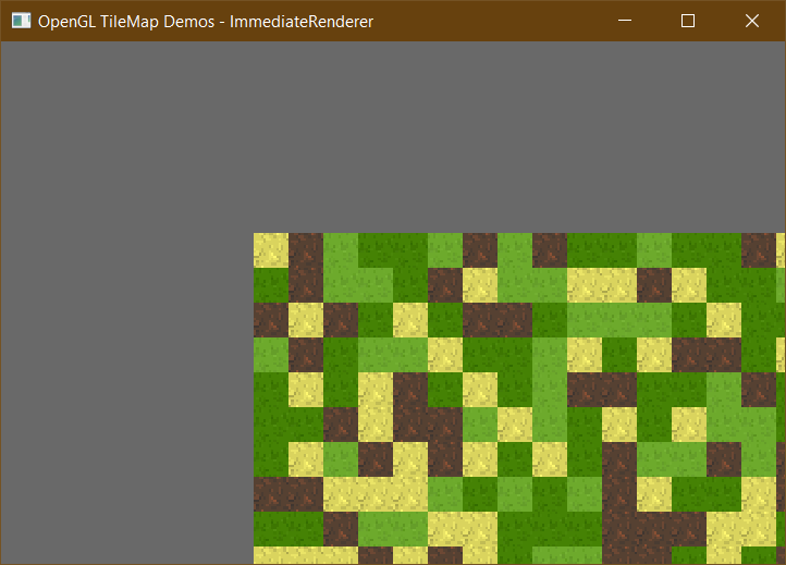
I hope to demonstrate in this repository different ways to render a tilemap onto the screen, and explain why some methods are preferred over others.
These are the different methods of rendering I intend on covering:
- Immediate Rendering (yuck!)
- Vertex-Buffered Rendering
- Element-Buffered Rendering
- Geometry Shader Rendering
For more information, see the official OpenTK Getting Started tutorials.
This shouldn't be done in real production applications. This is demonstrated to convey how OpenGL works under the hood. This method of rendering has been deprecated for years and it is a highly inefficient way of using the GPU.
The reason why it is inefficient is because it requires too many API calls to render even a simple primitive (e.g. a triangle) onto the screen. Each API call has overhead associated with it. This is because each API call is directed to your machine's GPU. So, instead of sending many (thousands or tens of thousands) relatively-small commands to the GPU (which probably complete in less time than the sum of their overhead), it makes more sense to send fewer, but larger commands.
Immediate rendering works by controlling the GPU (through OpenGL) in a very simple way. Using OpenTK, we can render a triangle onto the screen as such:
GL.Begin(PrimitiveType.Triangles);

GL.Color3(Color.Red); GL.Vertex2(0, -0.5);
GL.Color3(Color.Green); GL.Vertex2(-0.5, 0.5);
GL.Color3(Color.Blue); GL.Vertex2(0.5, 0.5);

GL.End();
Notice how many API calls it took to render a single triangle? Just imagine how many it would require to render a large 3D model or a game full of 2D sprites.
For more information, see the ImmediateRenderer.cs file.
A vertex buffer object can be defined simply as a block of memory containing vertex-related data allocated on the GPU's memory. "Vertex-related data" usually includes position data (e.g. x and y coordinates), texture coordinate data (e.g. which part of the texture to render) and color (e.g. what color to tint the texture).
Usually the first step is to initialize the data on the main memory (RAM; the non-GPU main memory), then to copy it to the vertex buffer object. Later the vbo (vertex buffer object) can be updated as the data changes.
Here is a sample of how data can be organized using interleaving:
# Each item in array represents a FLOAT
| x0 | y0 | tx0 | ty0 | x1 | y1 | tx1 | ty1 | x2 ...
Notice how each vertex has x, y, tx and ty attributes. The size of these attributes (in other words, the size of all the attributes of a single vertex is called stride). To get from x0 to x1 we would have to move stride number of elements to the right.
But this isn't the only way to organize the data, it can also be organized into multiple buffers. See below:
# Position buffer
| x0 | y0 | x1 | y1 | x2 ...

# Texcoord buffer
| tx0 | ty0 | tx1 | ty1 | tx2 ...
In fact, the x and y fields of each can also further be split, making a total of 4 buffers. For more information on the benefits of each arrangement, see the Wikipedia article Array of Structures vs Structure of Arrays.
In the code I used the first arrangement (using a single buffer). Now, once this buffer is made we need to somehow indicate which elements in the buffer correspond to what. OpenGL doesn't naturally know that the first item is x0, followed by y0 and tx0 and ty0... We need to make some clarifications.
This is done by using a vertex array object (vao). The purpose of this construct is to merely map the data inside of the buffer to positions in our shader code (more on this in a bit).
So, the vao is used to say that the first two elements in the buffer of every stride are position-data, and the next two elements are texcoord-data. Once this has been indicated, we will be able to use our buffer. To use the buffer we need a shader program.
Shaders are basically GPU programs. They're an OpenGL feature that allows you to run code on the GPU and use the data in that buffer you made earlier. This allows you to have more control over vertices and colors and such. In other words, since immediate rendering is deprecated, this is the proper method of customizing render logic -- by doing it on the GPU.
In this particular case the shader is very simple. The vao we made earlier maps the data from the buffer to the shader. This means we don't read that data from the buffer (e.g. as you would in a general purpose language using array indexing), rather it is directly initialized in our code as a global field known as an attribute. The shader used in the repository has two attributes: a position coordinate, and a texture coordinate.
It also has a uniform field, which is used to position the vertices on the screen according to the location of the camera using a matrix. The difference between a uniform field and an attribute field is that the uniform field is a shader-level constant (it can only change between various executions of the shader, but not during a particular execution) and the attribute field is a vertex-level constant.
Is it better than immediate rendering? It is faster than immediate rendering since it requires fewer API calls. But buffered rendering requires allocating memory on the GPU. But this is not a disadvantage, since buffering means you don't have to recompute what you already have. Besides, immediate rendering is deprecated. Buffered rendering is better than immediate rendering.
For more information, see the VertexBufferedRenderer.cs file and see OpenTK's Hello Triangle tutorial.
This piece is quite straightforward. If you understand how Vertex Buffer Objects work, then Element Array Buffers will be a piece of cake. The latter allows you to reuse vertices defined in your vbo by referencing them by their index.
The indices are populated into an array whose elements are of type byte, ushort or uint. Then once the eab has been created and binded, the indices can be copied to the GPU using the GL.BufferData function.
This allows you to render a quadrilateral (which is two triangles) using 4 vertices rather than 6. For example:
# if this is your vertex buffer object,
# (the points below represent a square)
| 0, 0 | 10, 0 | 10, 10 | 0, 10 |

# then this would be your element buffer object:
| 0 | 1 | 2 | 1 | 2 | 3 |

# the first triangle is marked by vertices 0, 1, 2
# the second triangle is marked by vertices 1, 2, 3
For more information, see the ElementBufferedRenderer.cs file.
This method is great. Instead of copying position or texcoord data to the vertex buffer (allocated on the GPU), we only copy the tile-ids. In this demo, a tile-id is a byte (unsigned) and each tile-id corresponds to one vertex. The drawing mode is POINTS (not TRIANGLES).
Using the geometry shader, we can convert each vertex (which is a single tile-id) into two triangles (which make up the square tile). This is done mathematically and it's feasible because the tile map has a uniform structure. In other words, given a map size of 64x64 (using column-major ordering) we can deduce that the tile with index 65 should be at coordinates (1, 1), where as index 66 would be at (1, 2) and 67 would be at (1, 3), and so on. This demonstrates that we can find the position of a tile on the GPU.
This begs the question -- since we're only passing the id of the tile (which is used to determine which image we display), how do we determine the index that a tile/vertex is at in the buffer? This is done in the vertex shader using the global value: gl_VertexID (docs). This is a 0-indexed integral value that holds the index of the tile/vertex. This is the magic field that allows us to calculate the positions of the two triangles that make up the tile.
This method uses much less GPU memory than the prior two methods, and the code is simpler as well.
For more information, see the GeometryRenderer.cs file and the similarly named shader files in the resources directory.
- Partition your map into smaller chunks. Let's say each chunk is 16 by 16 tiles. The fact that this is a constant will mean you dont have to pass the
mapSizeto the shader. Rather, the chunk size can be hard coded. - Since the chunk size is a multiple of 2, don't use division or modulus in the GeometryRenderer.vert to determine the
xandypositions, instead use bitwise operations. (I included these in the shader, but they're commented out.) - Only draw chunks that are visible to the user. If you've allocated a separate buffer for each chunk, then only draw the buffers that are within the view of the camera. If you've allocated one big buffer, but have a clever way of ordering chunks in it, you can use the last 2 parameters of the DrawArrays function, which allow you to specify which vertices to draw.
- If you want to use more tiles use a
ushort(unsigned 16-bit integer) for the tile-id instead of abyte(unsigned 8-bit integer). This will take up twice as much GPU memory for a map of the same width and height. You will have to increase your tileset texture accordingly. The one in the demo assumes that the tileset contains 256 tiles arranged in a grid of 16 by 16. You can, for instance, make 4 tilesets of 128 by 128 tiles (fitting them all into one tileset might make the texture too big, beware of texture size limits). All four tilesets can be bound to four texture units, and you can assume that the last 2 bits in the tile-id determine which of the four tilesets to use, and the first 14 bits determine which tile in that tilese to use. This design might be overkill, especially if you don't need this many tiles.
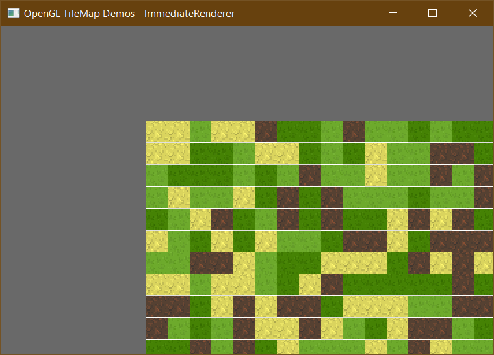
Notice how there are lines between the tiles in the image above? Sometimes these horizontal and vertical lines appear. Don't worry, it's fairly easy to fix.
Why does it happen? This happens because you're performing sub-pixel rendering without using texture borders. This causes OpenGL to read/take a pixel from the texture that don't fall into the boundaries of the tex-coords for a given tile. In other words, when a sub-pixel is rendered on the boundary of the tile, OpenGL assumes that you'll want to retrieve a pixel on the boundary of your texcoords. In texture atlasses this can be a problem, since that one pixel can mess up your tile map -as seen above.
How can I fix it? In this repository the sample tile set texture is a grid of 16-by-16 tiles. This means that the top-left-most tile has the following source rect: (x0=0, y0=0, x1=1/16f, y1=1/16f). In fact, for any given tile referenced by its integer coordinates from 1 to 16, (xi, yi), we can find its source rect using the following equation: (x0=xi/16f, y0=yi/16f, x1=(xi+1)/16f, y1=(yi+1)/16f).
This lines-between-tiles bug can be fixed by performing a correction on the texcoords by adding a small padding: e.g. 1 / 256f. So, the x0 and y0 fields will be increased by that padding amount, whereas the x1 and y1 fields will be decreased by it. The equation then becomes: (x0=xi/16f+1/256f, y0=yi/16f+1/256f, x1=(xi+1)/16f-1/256f, y1=(yi+1)/16f-1/256f)
This fix has already been comitted into the repository, so you probably won't even see this problem to begin with.

