This project design to mine Duino-Coin using an Esp8266/Esp32 as a master and Arduino as a slave.
Using the I2C communication to connect all the boards and make a scalable communication between the master and the slaves.
DuinoCoinI2C -> DuinoCoin Version 2.7.3
All Slaves have the same code and should select the I2C Address automatically.
- DuinoCoin (Handle the
Ducos1ahash work) - ArduinoUniqueID (Handle the chip ID)
- StreamJoin (StreamString for AVR)
The I2C Address on the Arduino is automatically updated when the board starts, if an Address already exists on the I2C bus the code finds another Address to use.
Tiny Slaves have the same code and the I2C Address is selected by the EEPROM.
- ArduinoUniqueID (Handle the chip ID)
The code has some defines to make the code smaller and disable some features.
This enable the Serial Monitor.
#define SERIAL_LOGGER Serial
This enable the led output and makes de led flash when the slave is working.
#define LED LED_BUILTIN
If the Serial is enable on your mcu, you could send the I2C Address using the Serial Monitor.
You could use this code to generate a ATtiny85 slave using the http://drazzy.com/package_drazzy.com_index.json boards on the Arduino IDE.
Check the ATTinyCore project for more information.
| pinOut | ATtiny85 |
|---|---|
SCL |
PB2 |
SDA |
PB0 |
I2C Address is selected by the EEPROM_ADDRESS (default 0) and the first upload the Address is set by the define.
#define ADDRESS_I2C 1
The master requests the job on the DuinoCoin server and sends the work to the slave (Arduino).
After the job is done, the slave sends back the response to the master (Esp8266/Esp32) and then sends back to the DuinoCoin server.
- ArduinoJson (Request Pool Version 2.6)
- ESPAsyncWebServer (ESPAsyncWebServer)
- ESPAsyncTCP (ESP8266)
- AsyncTCP (ESP32)
- SSD1306Wire (SSD1306Wire)
The code supports 10 clients and can be changed on the define:
#define CLIENTS 10
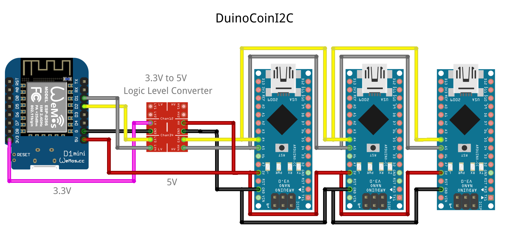
Connect the pins of the Esp8266 or Esp32 on the Arduino like the table/images below, use a Logic Level Converter to connect between the ESP and Arduino.
| ESP8266 | ESP32 | Logic Level Converter | Arduino | |
|---|---|---|---|---|
| 3.3V | 3.3V | <---> | 5V | |
| GND | GND | <---> | GND | |
SCL |
D1 (GPIO5) | GPIO22 | <---> | A5 |
SDA |
D2 (GPIO4) | GPIO21 | <---> | A4 |
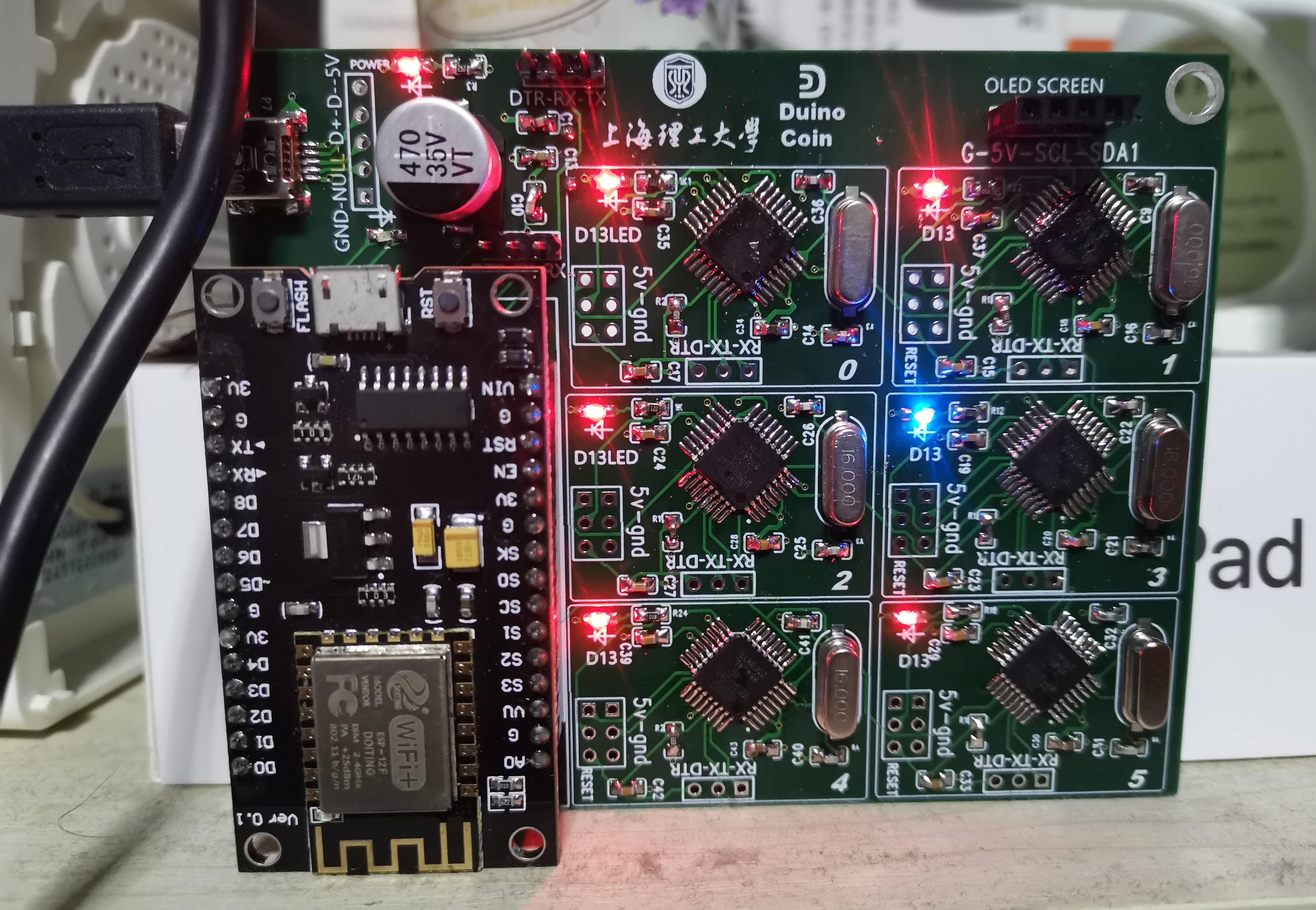
ericddm shared this amazing pcb!
Do you like this project? Please star this project on GitHub!

