Design files, 3D models, and ZMK firmware for the Qimera Keyboard
For this section, I will assume that you already have the basic soldering station setup with you. If not, please look into getting a good soldering iron, solder wire (lead free if possible), fume extractor, soldering flux, solder wick and/or desoldering pump (to fix any mistakes made while soldering).
-
PCB: I designed a custom reversible PCB for this keyboard. There are a few options for you to get access to the design files:
- I ordered my PCBs from OSH Park as I wanted the PCBs to have a cool look with black core and transparent solder mask (check out their 'AfterDark' service) so that the copper layers which contain the wiring and art are visible. You can order directly from my shared project on the OSH Park website.
- If you want to use a different vendor, you can find the zipped Gerber files in the
pcbsfolder. - If you know your way around designing a PCB, you can customize your the PCB on your own by opening the PCB in KiCad or any other compatible PCB design software. Please find the KiCad project files in the
pcbsfolder.
-
Functional components: The following components I ordered directly from typeractive.xyz
- Key switches - qty. 54
- NOTE: The PCB is specifically designed for Kailh Choc v1 switches. I personally used the Kailh Pro Red switches.
- NiceNano v2 MCU - qty. 2
- EZ solder MCU sockets - qty. 2 (one pair of sockets for each MCU)
- Kailh low profile keycaps - qty. 54 (make sure to include at least two homing keycaps if you need them!)
- Kailh hotswap sockets - qty. 54
- Right angle JST 2.0 battery connector - qty. 2
- SMD SPDT (On/Off) switch - qty. 2
- Momentary switch for resetting the MCU - qty. 2
- SMD diodes - qty. 54
- Tenting feet - qty. 4
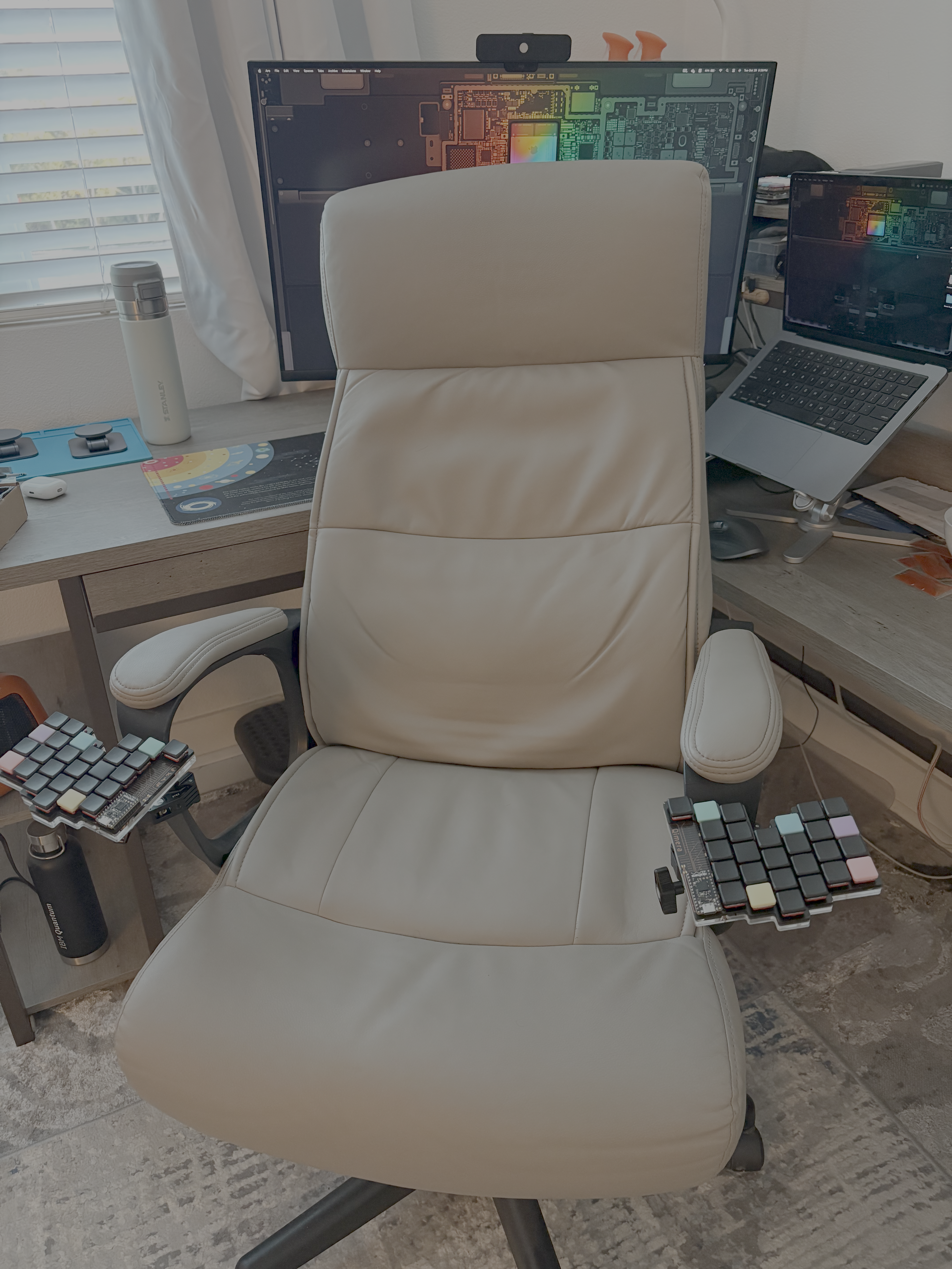
- NOTE: Instead of getting these tenting feet from typeractive, I got some magsafe iphone mounts that come with a magnetic ring that can be stuck onto the bottom of the enclosure. This gives more flexibility for keyboard mounting options. I also purchased a magsafe puck with a 1/4 inch screw hole and some camera clamp mounts, so that I could mount it on my chair for max comfort! (see the last pic on top)
- Battery - qty. 2
- You can buy either of the batteries (750mAh or 110mAh one) from typeractive and they would fit well in the enclosure.
- NOTE: I chose to get neither of the aforementioned batteries. I instead got these 1800mAh ones as I wanted the battery life to be in 'years' and not weeks :P
- Key switches - qty. 54
-
Keyboard Enclosure:
- For this build, I chose to go with a easy to assemble laset cut enclosure ordered from SendCutSend.
- You can find three design files in the
casesfolder:- Top plate(
cases/Qimera top plate.dxf): I recommend to get this made in 0.8mm - 1.2mm thick mild steel. The thickness of this plate is CRITICAL, because if the plate is thicker, the Kailh Choc switches won't snap into the top plate. You can choose a particular finish for it too. I went with 'Black Zinc' coating to make it look a bit nicer! :) - Battery plate(
cases/Qimera battery plate.dxf): I got this made in 4.5mm thick transparent acrylic material so that the keyboard has a see-through back for the PCB art to be visible. - Bottom plate(
cases/Qimera bot plate.dxf): I got this made in 3mm thick transparent acrylic material so that the keyboard has a see-through back for the PCB art to be visible.
- Top plate(
-
Travel Case:
- You can find the travel case in
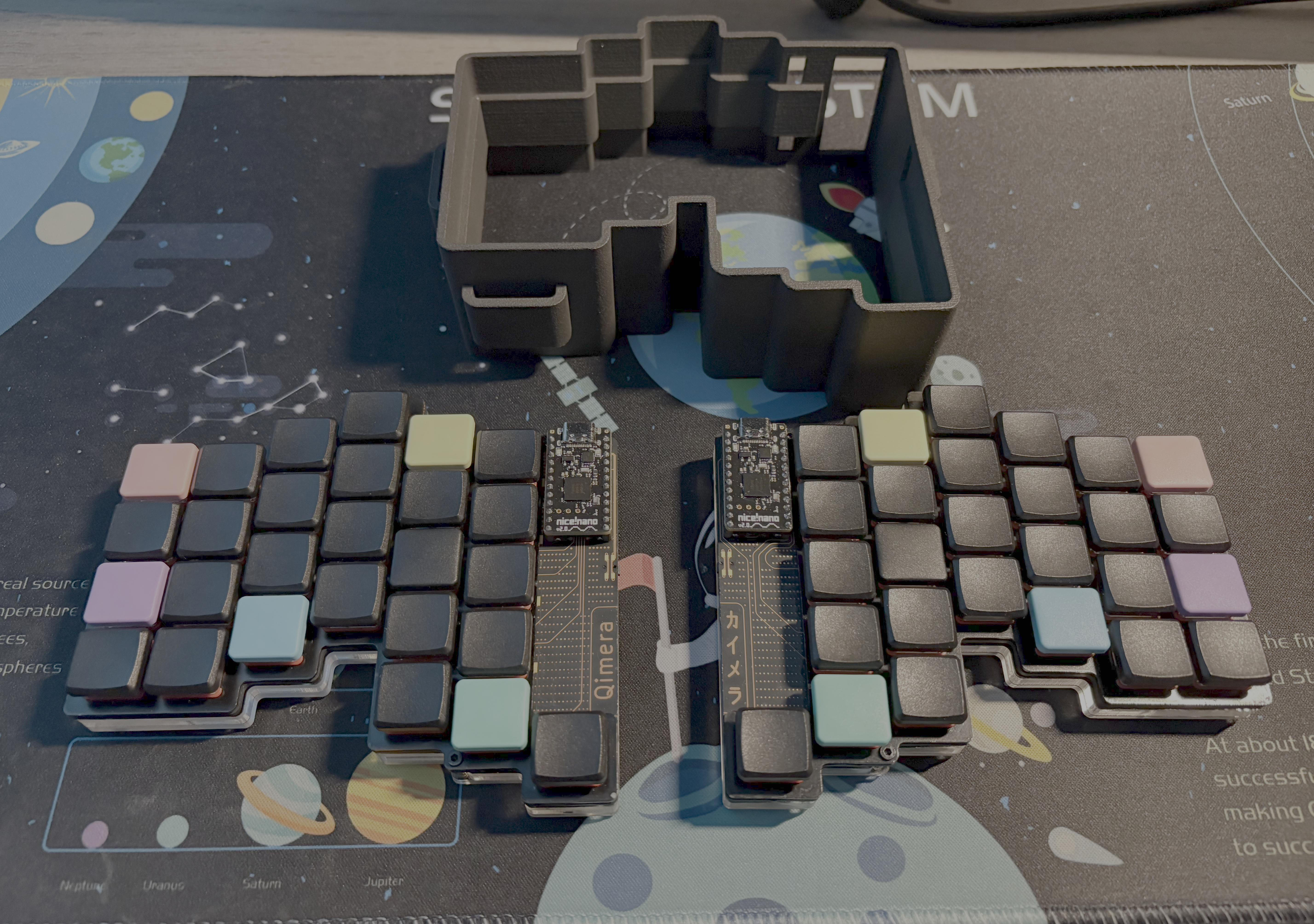
cases/Qimera travel case.stland it can be printed using any conventional 3D printer. - The travel case is designed to have some loops on the sides, through which you can pass a velcro strap to secure the two halves of the keyboard together and ensure that they don't fall out!
- You can find the travel case in
- The PCB is reversible and needs some extra caution while soldering items:
-
For diodes, power switch, and reset switch:
- Please make sure that all these are soldered on the SAME side of the PCB. This side will now be defined as the BOTTOM side of each PCB from here on. If soldered on the top side, there is a chance that the enclosure top plate wouldn't sit properly in between the PCB and the switches.
- Also, ensure that the diodes are lined correctly while soldering them, i.e. the line on the diode matches the line on the silkscreen on which you are soldering the diode.
-
For the MCU:
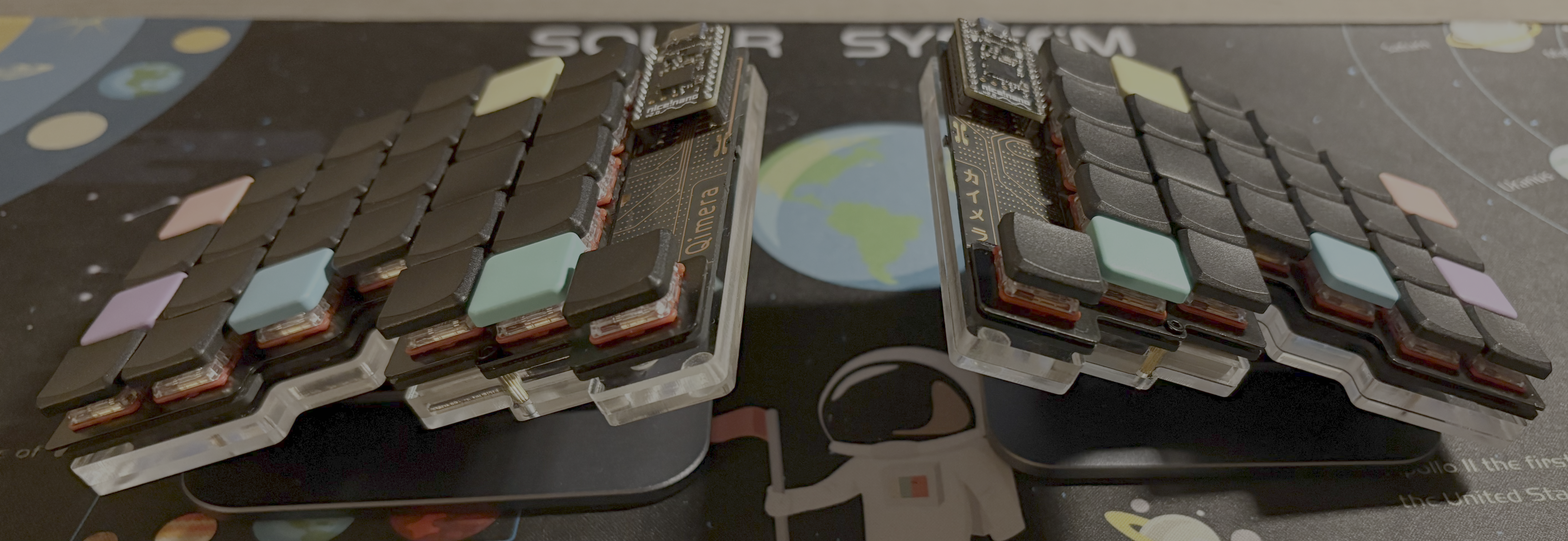
- The MCU needs to go "Face Up" (i.e. the side with the microchips on MCU should face up on the keyboard, see the pictures above for reference.)
- If you think you're ready to solder the MCU now, STOP!!
- Since the MCU footprint is made to be reversible, the actual row and column connections of the keyboard are connected to the line of vias on the inner side of the MCU and not where the actual MCU pins get soldered.
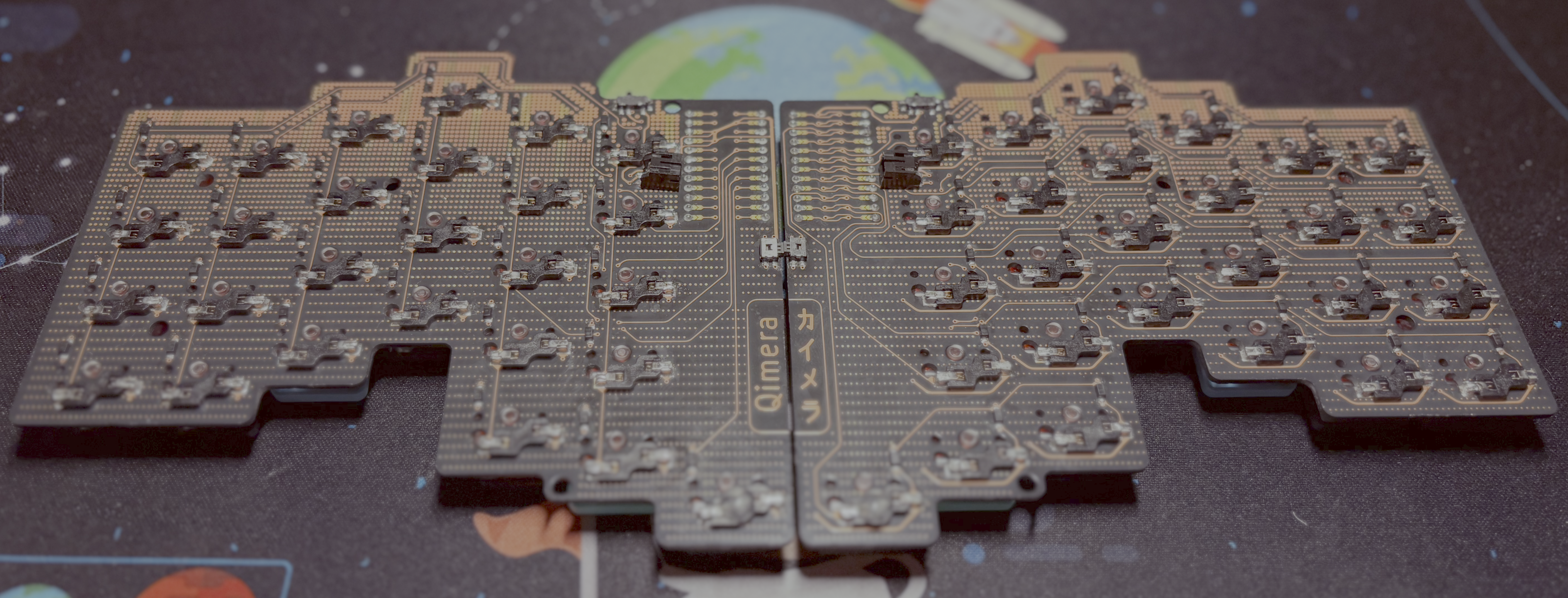
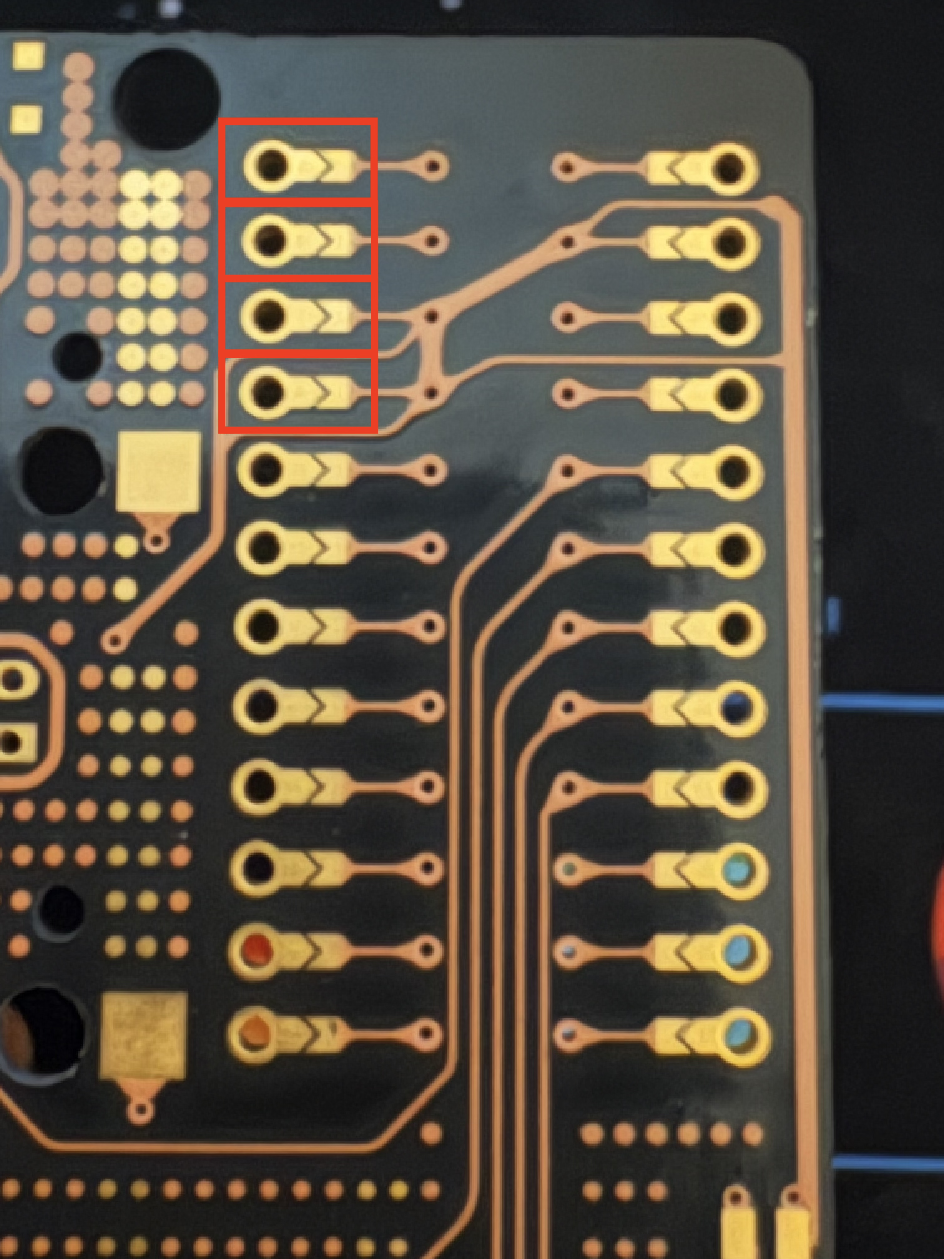
- Therefore, to actually make the connections, there is a set of jumpers connected to each pin of the MCU (see the structures in the image below marked in RED.)
- ALL OF these jumpers need to be connected on the TOP side of each PCB with a dab of excess solder bridging the two metal parts in gold color.
- WARNING!!: This is the most CRUCIAL step and you need to BE CAREFUL while soldering the jumper as just a little accidental flick of the soldering iron or a bit of excess solder could lead to the solder overflowing into the MCU pin hole on the side, which would make things difficult while soldering the MCU socket later on.
- NOTE: here the TOP side refers to the side of the PCB which is opposite to the side having the diodes, power switch and reset switch soldered.
- After this tedious and important step, begin socketing the MCU by first soldering the socket in place, then placing the mill-max pins, and then placing the MCU on top and soldering it into the socket.
- Make sure that the MCU is removable from the socket, and then re-attach it by pressing it in firmly.
-
For the JST 2.0 battery connector:
- Make sure to connect the battery connector on the bottom side of the respective PCBs (same side as the diodes, power switch, and reset switch)
- After soldering the battery connector, you will notice jumpers similar to ones near MCU. These are to ensure that the battery is connected to correct polarity when you flip one of the PCBs to use it for the other half of the keyboard.
- Do a similar thing for connecting the jumpers near the battery connector, but this time the jumpers should be briged on the BOTTOM side of each PCB (the BOTTOM side being the same side with diodes, power and reset switch).
-
For ease of use, I'm also including my ZMK config. Since, I keep changing my personal config too often, I would recommend to click on the zmk-config-qimera submodule and fork that repo to make your own copy of the config.
- You can now either directly edit the config and GitHub actions will build the firmware for your config, or you can use a keymap editor tool like this and connect it with your forked repo to change the keymap. Once the firmware is built, it should show up in the
Actionstab of the repo and you can download it from there. - Connect the left half of the keyboard to you computer via a USB-C cable, double press the reset button to put NiceNano MCU into bootloader mode, and then drag and drop the compiled UF2 firmware for the left half of the keyboard.
- Do the same with the right half.
- After powering up the keyboard for the first time, click the reset button on both halves simultaneously, and they should get paired to each other.
- Then you can proceed to pair the keyboard through bluetooth, to whatever device you like!
