Designing an Audio Amplifier
Status: Completed Type: ELE504 Lab
Objective
The objective of this lab was to design a practical audio microphone amplifier. At the same time the DC imperfections of the LM741 Op-Amp were investigated and strategies to minimize the overall DC effects were implemented.
Comparisons of different types of Op-Amps were also made, mainly between the LM741 and the LM318. The frequency response and the slew rate limitations of each Op-Amp were investigated.
The goal was to design the circuit in such a way that the slew rate and cutoff frequency limitations of the op-amp do not affect the signal. Later on taking into account the DC offset when working with microphones.
The specifications of the circuit are: Vi = 10mv (pk-pk) Vo = 5V (pk-pk) Desired Bandwidth = 100Hz - 20kHz Aclo = 500 V/V
The audio amplifier will either be made from an LM741 or LM318, eventually I chose to use 2 LM741’s since I only had those available to me at the time.
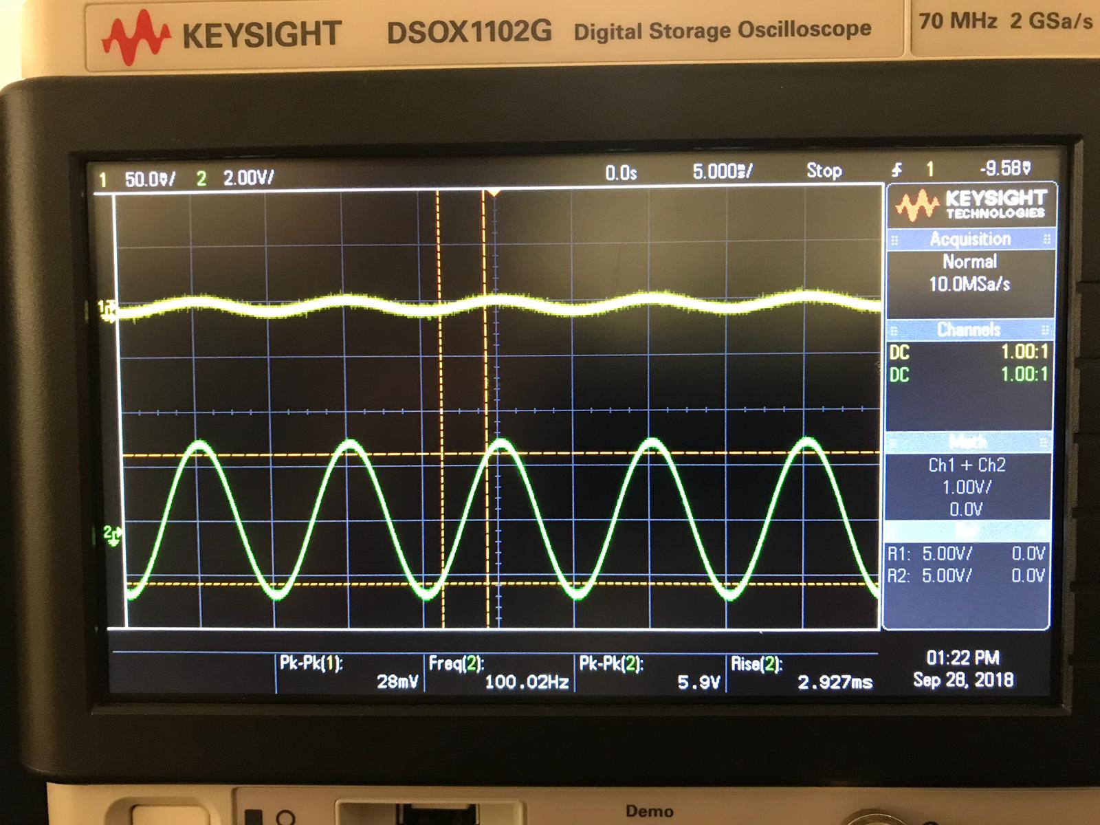
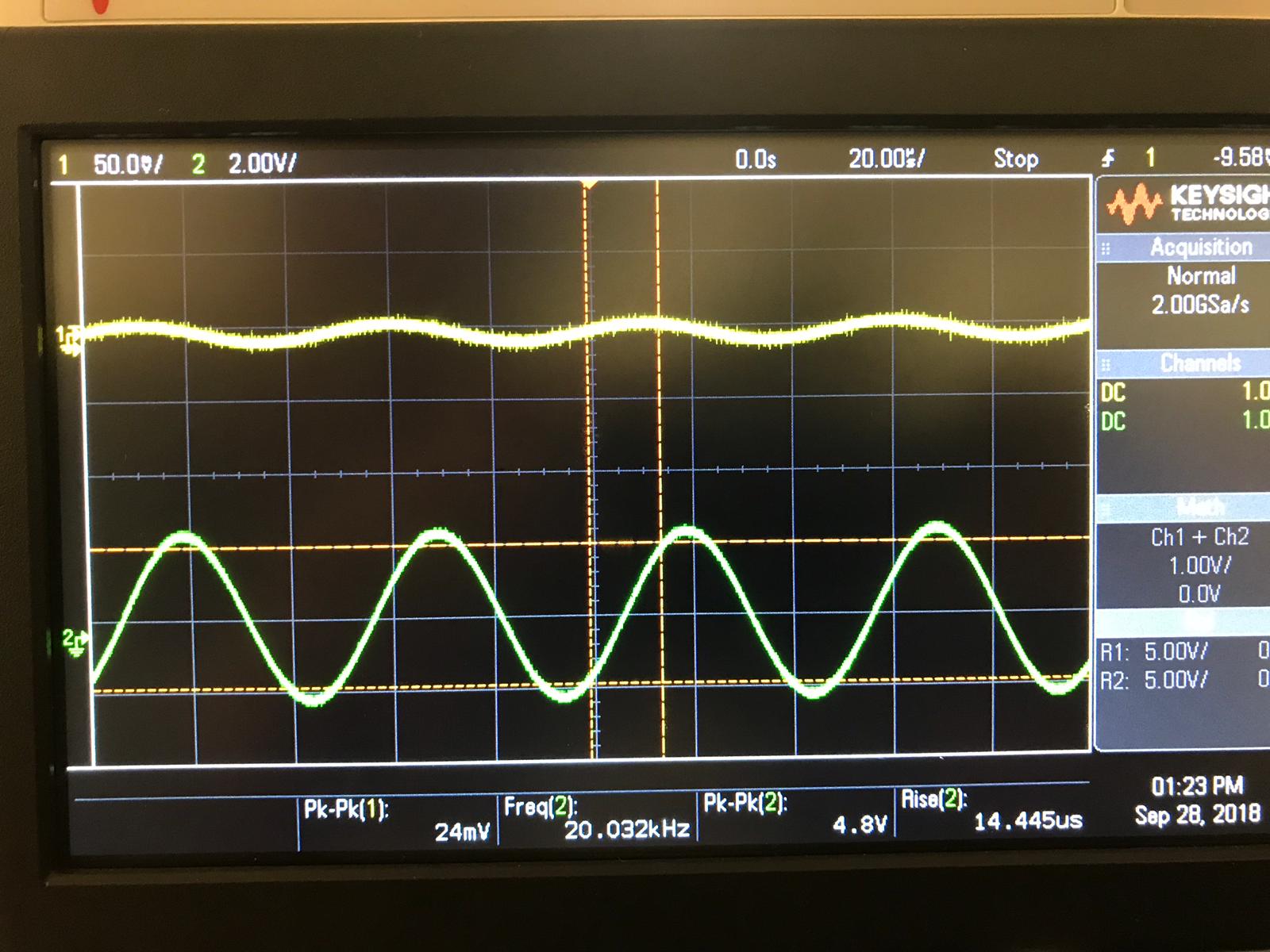
Tests and simulations as well as lab work were done for the LM741 circuit. As seen in the oscilloscope screenshots the circuit works well to amplify the signal within the desired bandwidth (100Hz - 20kHz).
The next step of this project would be to use an actual microphone and amplify its sound so that it is audible in a small speaker.
Microphone planning to use => Electret microphone, Model #: 07-9 Speaker planning to use => McBridge AZ-30s.
Calculations of Audio Amplifier with both LM741 and LM318
NOTE: For better visual clarity the equations will soon be typed in LaTex
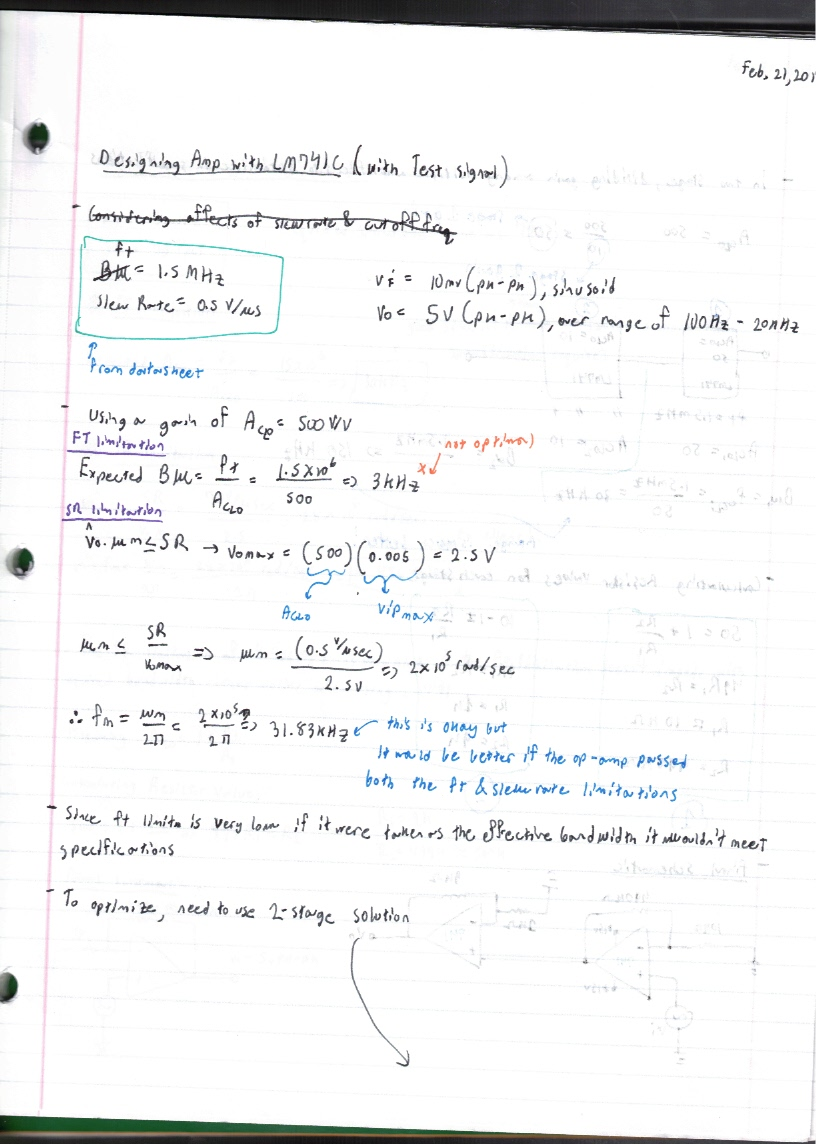
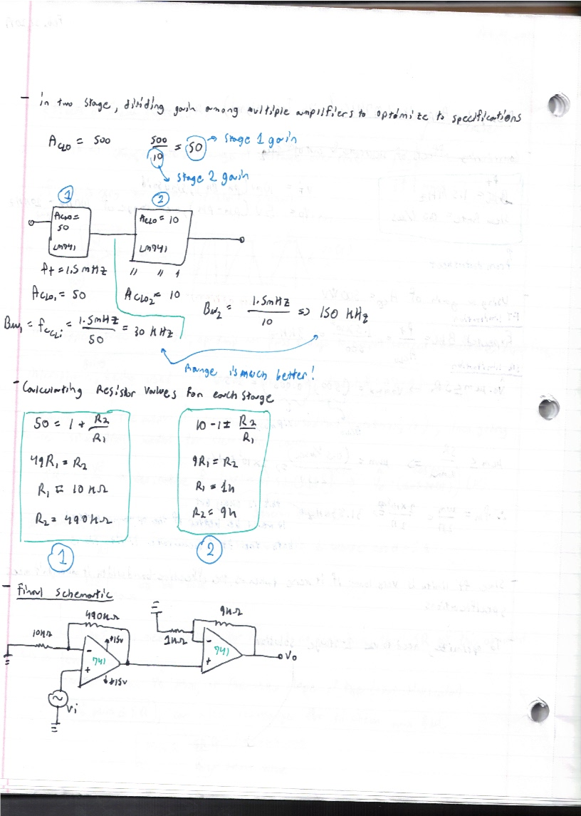
For the LM741
The image above is page 1 of the calculations LM741.
The image above is page 2 of the calculations for LM741.
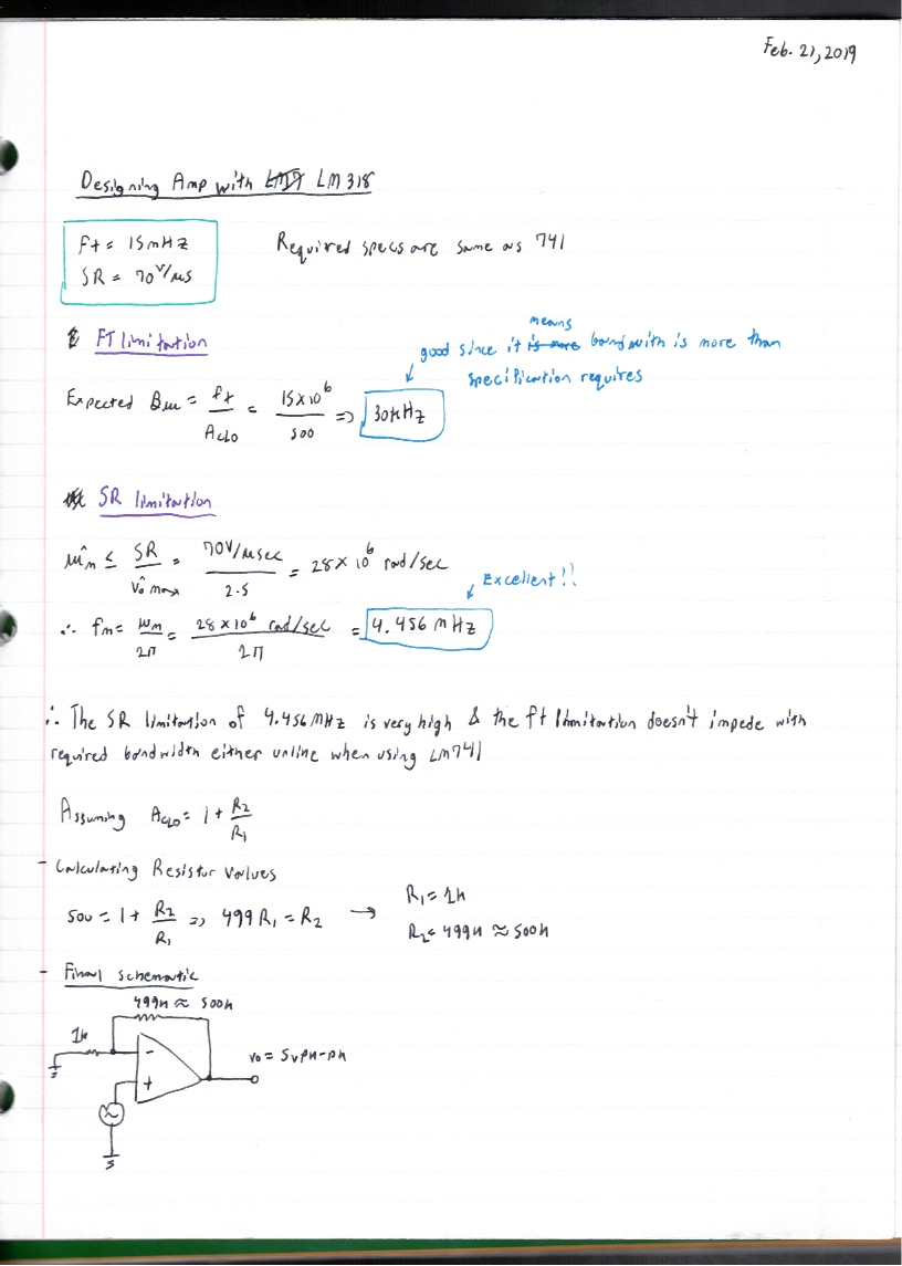
The image above is page 1 of the calculations for LM318.
For this project I will be going with the LM741 version of the amplifier circuit. Even though the LM318 version of the circuit is cheaper since only 1 op-amp is needed as opposed to 2 LM741 Op-Amps at this time I only have LM741 op-amps at my disposal.
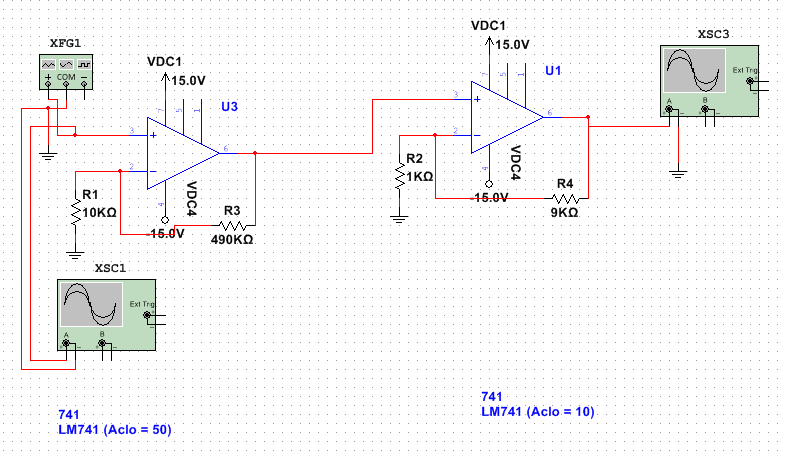
Simulation in NI Multisim
Circuit Being Simulated
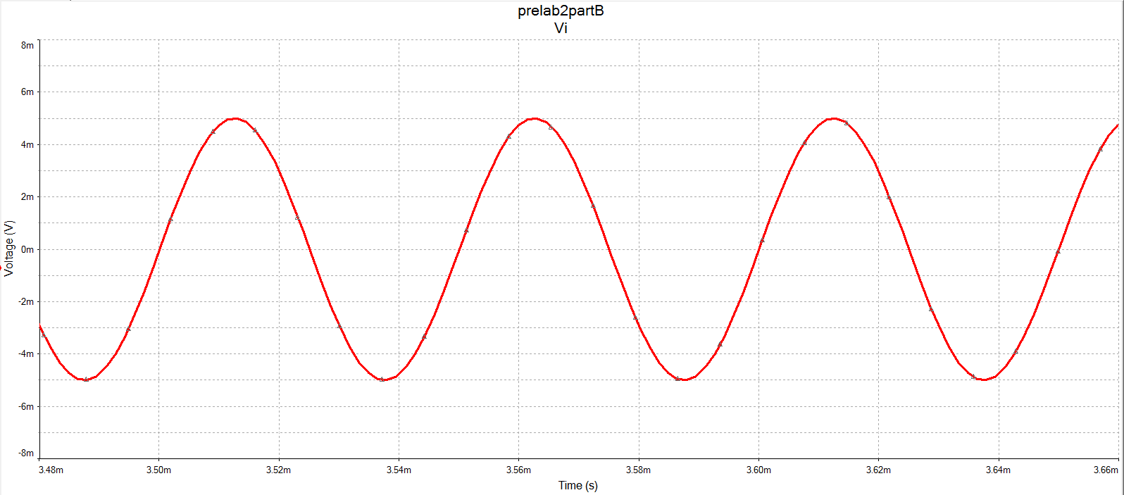
Input Voltage (10mV (pk-pk) @ 20kHz):
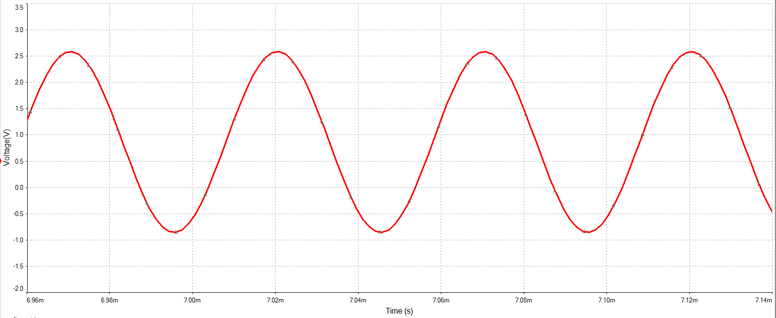
Input Voltage (5V (pk-pk) @ 20kHz):
In conclusion the schematic seems to be working well in simulation, therefore it is time to build it and see if the results hold in the real world.
Building the Circuit and Testing the Properties
Circuit being built:
Oscilloscope Results
NOTE: The yellow traces are the input waveforms, whereas the green traces are the output waveforms.
Waveform results @ 100Hz:
Waveform results @ 20kHz:
Conclusion
It seems that LM741 amplifier circuit is working according to specifications.
Therefore the next step after this will be to apply the microphone and speaker circuitry and observe if it correctly amplifies the voice / input audio source.
However it should be noted that further calculations will have to be made to avoid distortion and noise. I am mainly talking about the potential for DC offset and bias currents, which will have to be nulled out.
