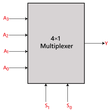
In 4:1 multiplexer, there are four inputs, $A_0$ , $A_1$, $A_2$ and $A_3$, 2 selection line, $S_0 , S_1$ and single outputs, Y. On the basis of the combination of inputs at the selection line $S_0$ and $S_1$, one of these 4 inputs will be connected to the output.

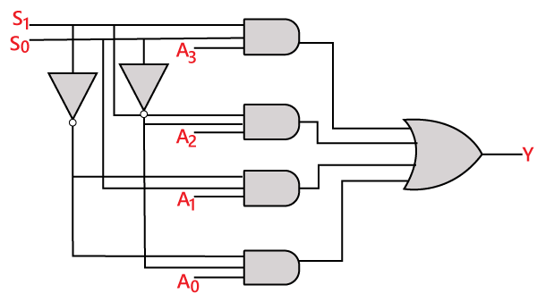
$$Y=\overline{S_1} .\overline{S_0}. A_0+\overline{S_1}. S_0. A_1+S_1 .\overline{S_0}. A_2+S_1 .S_0. A_3$$
| $$S_0$$ |
$$S_1$$ |
$$Y$$ |
| 0 |
0 |
$$A_0$$ |
| 0 |
1 |
$$A_1$$ |
| 1 |
0 |
$$A_2$$ |
| 1 |
1 |
$$A_3$$ |