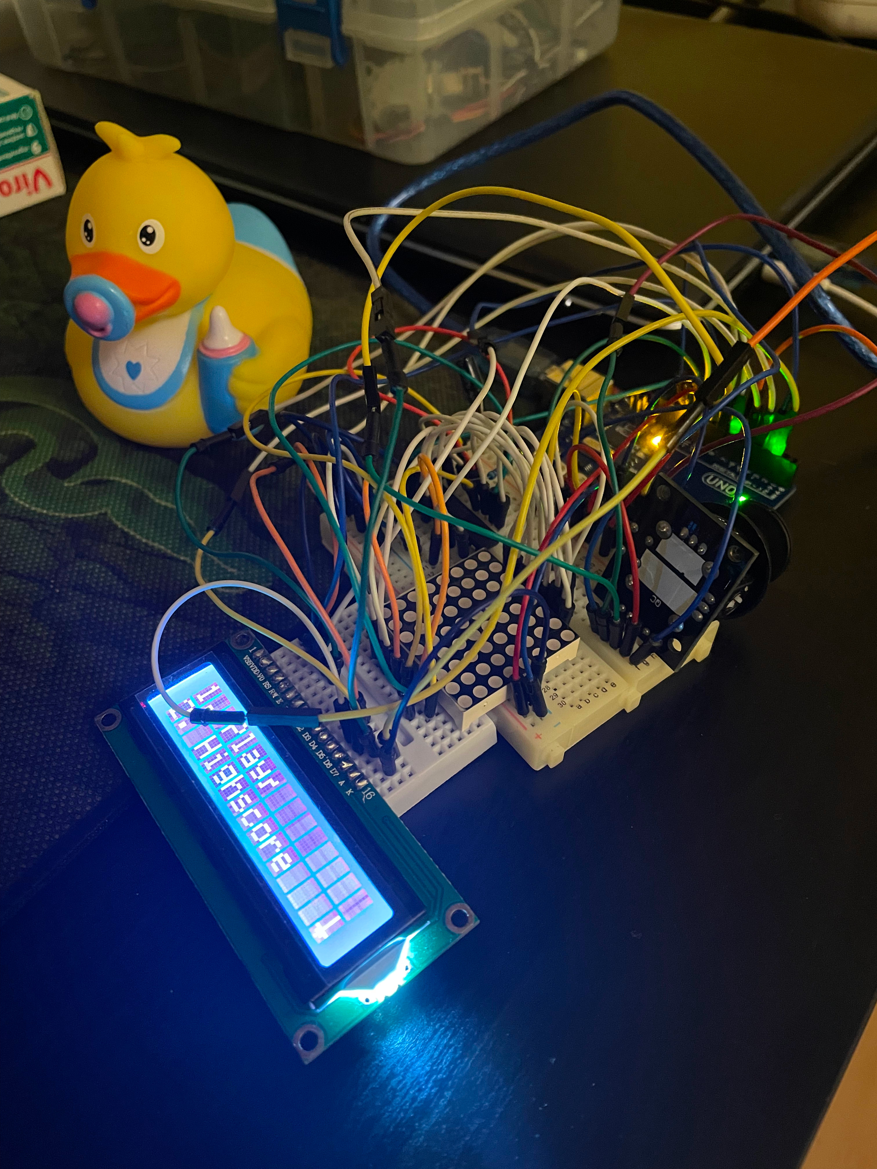
Learning interesting stuff about robotics.
The code for this homework can be found here.
Task requirements:
- there will be 3 potentiometers, each of which corresponding to an RGB color
- gather input from each of the potentiometers
- properly map the value from a
0-1023range to a0-255range - send the converted value to the right output PIN
The set-up:
The video showcasing the functionality can be found here.
Interesting challenges:
- there is a single 5V pin on the Arduino board and 3 different potentiometers which require a source; then I recalled how a breadboard works and found the solution: to use the + and - columns
The code for this homework can be found here.
The task is to build a simple traffic lights system.
Task requirements:
- 2 LEDs for people lights
- 3 LEDs for cars lights
- 1 buzzer
- one button
The set-up:
The video showcasing the functionality can be found here.
I was tempted to refactor common logic into separated functions. For instance, I'd encapsulate these lines in a beepBuzzer function:
if (isBuzzerActive) {
  tone(BUZZER_PIN, 1000);
} else {
  noTone(BUZZER_PIN);
}

unsigned long elapsedBuzzerTime = millis() - buzzerStartTimestamp;
if (elapsedBuzzerTime > BUZZER_STATE3_INTERVAL_MS) {
  isBuzzerActive = !isBuzzerActive;
  buzzerStartTimestamp = millis();
}
However, the problem I had encountered was that the function could not be 100% pure. As in, beepBuzzer might need a beepInterval, but 1) it can't be declared in the function's body and 2) the beepInterval might also be different, depending the context the function is used in(i.e. different stages require different intervals). So, I decided that it wasn't worth it.
The code for this homework can be found here.
The set-up:
The video showcasing the functionality can be found here.
The code for this homework can be found here.
The set-up:
The video showcasing the functionality can be found here.
The code for this homework can be found here.
The set-up:
The video showcasing the functionality can be found here.

