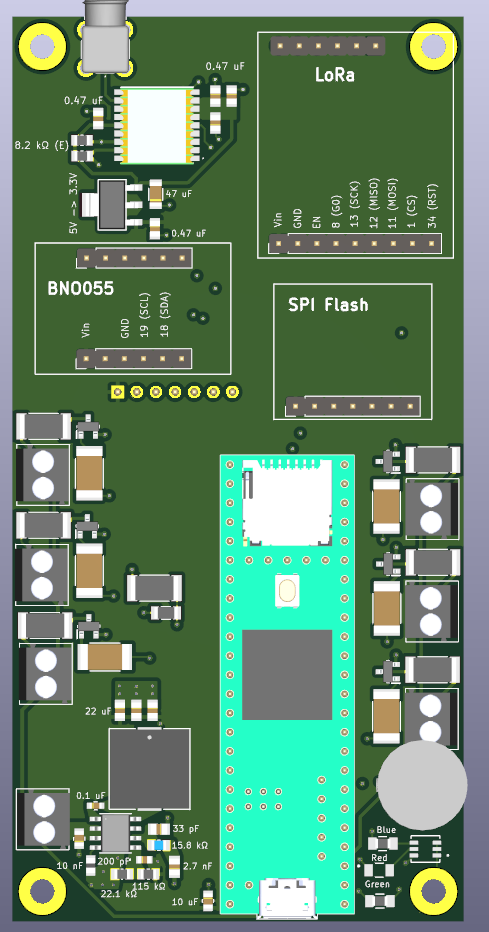
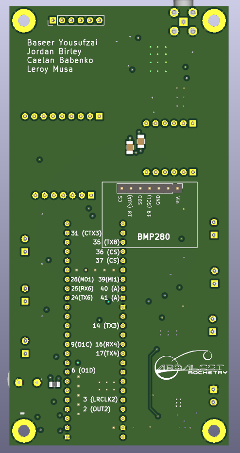
This repository contains the code and documentation for the flight computer used for our 2 Stage High Power Rocket set to launch at Launch Canada 2024
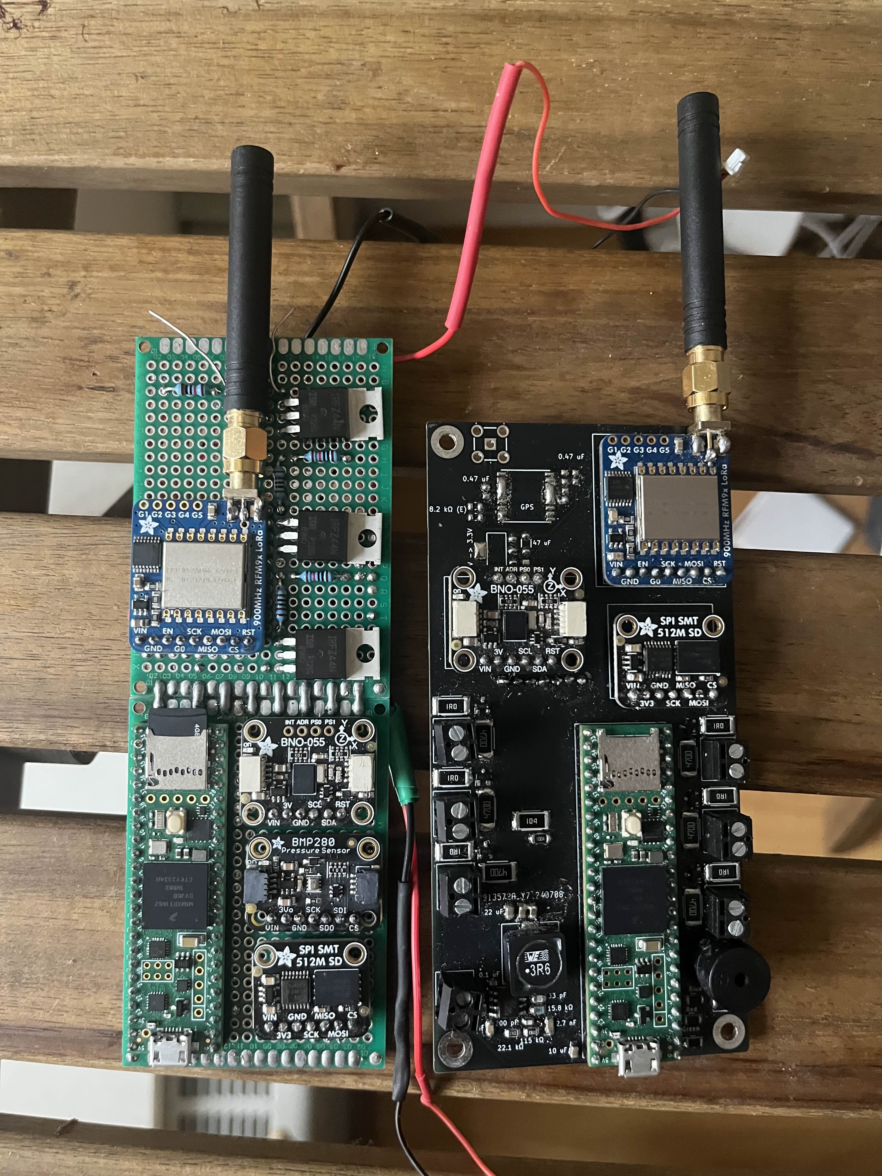
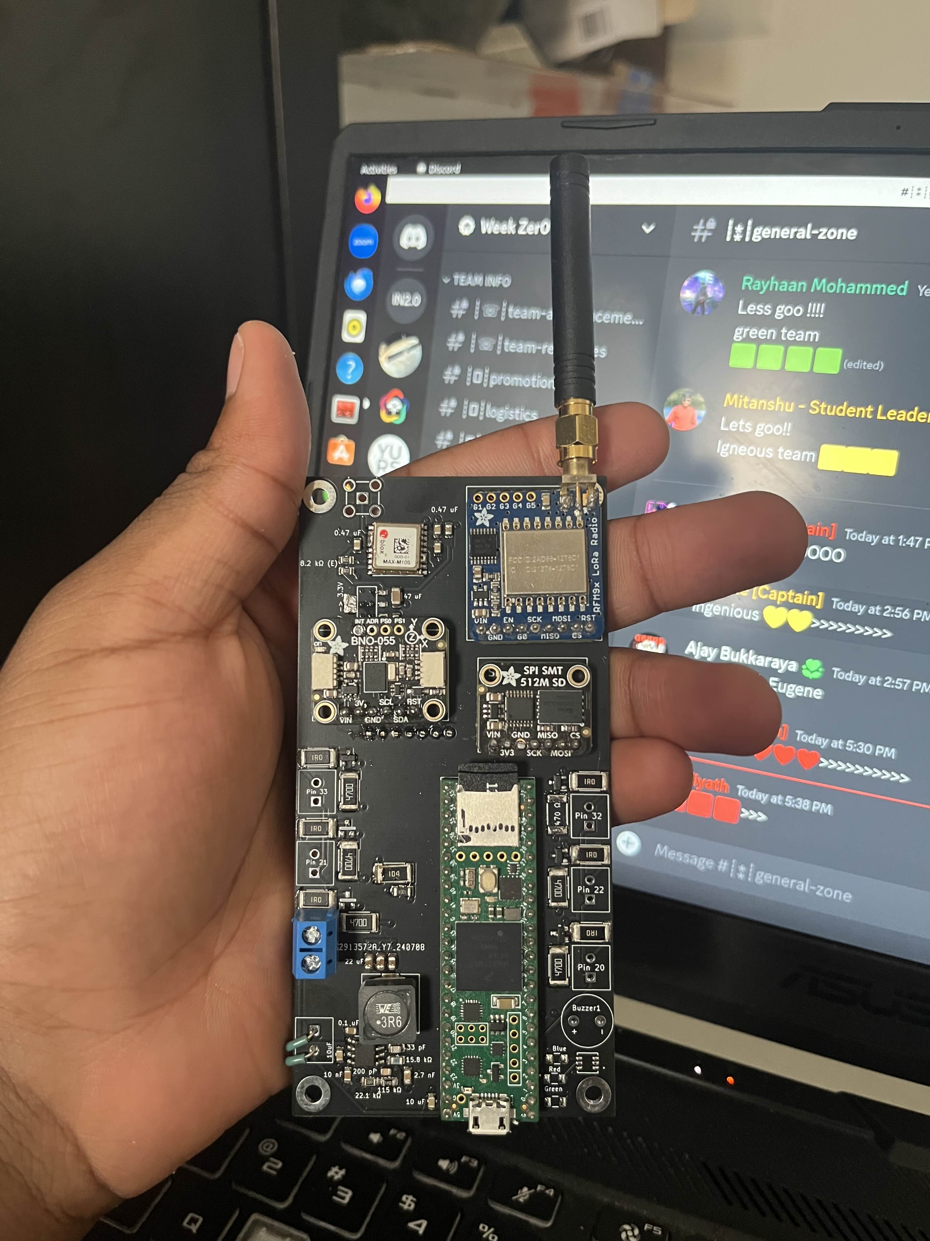
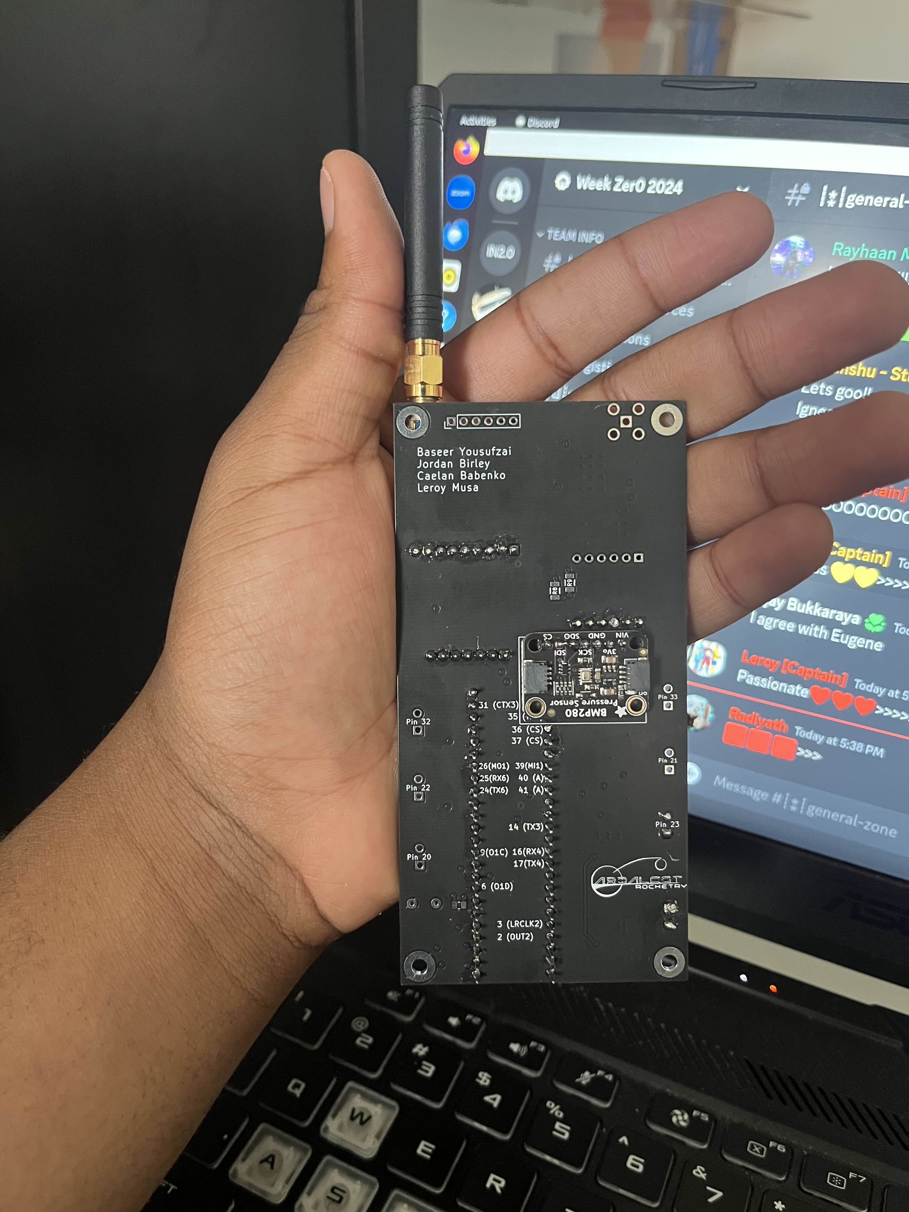
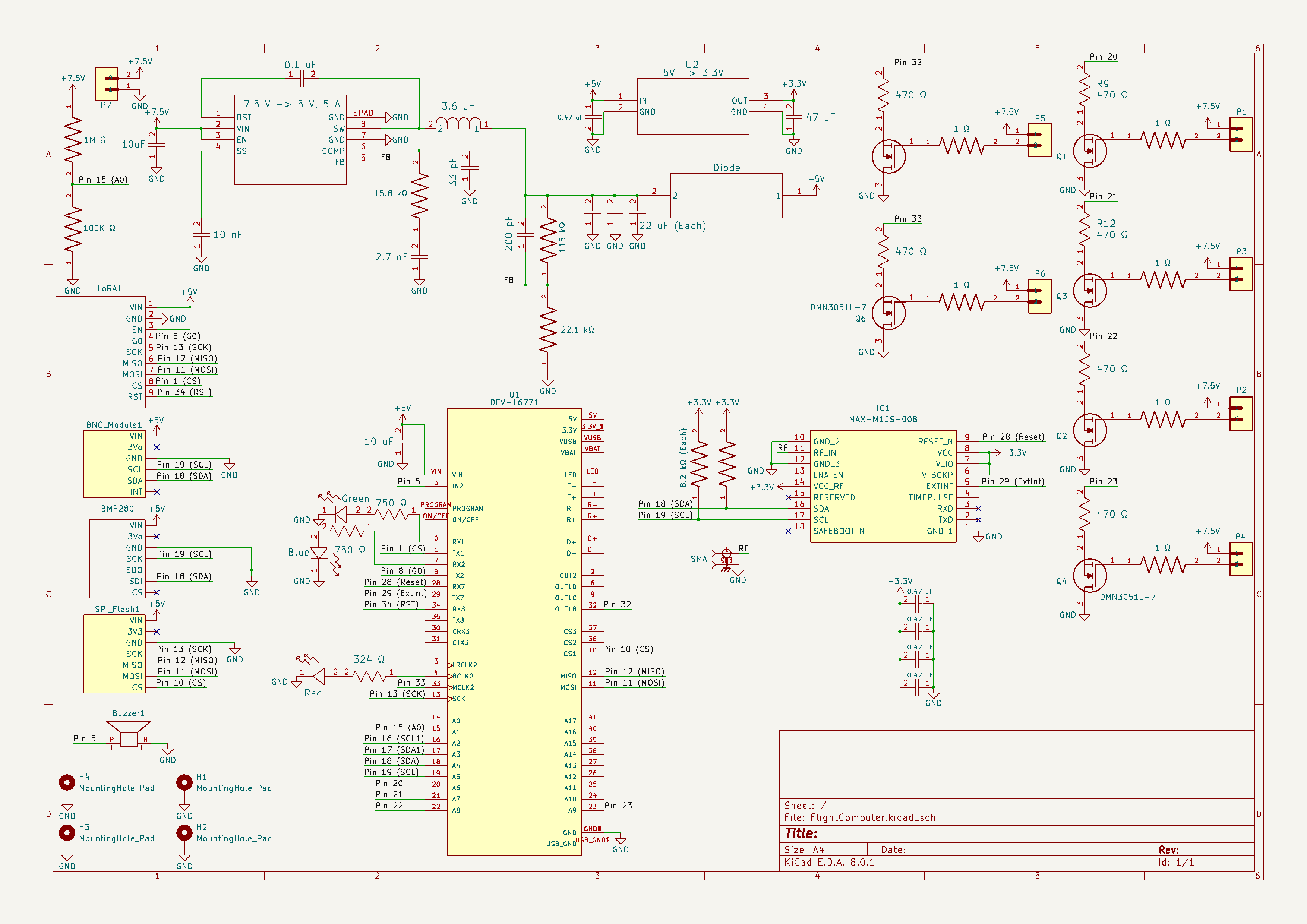
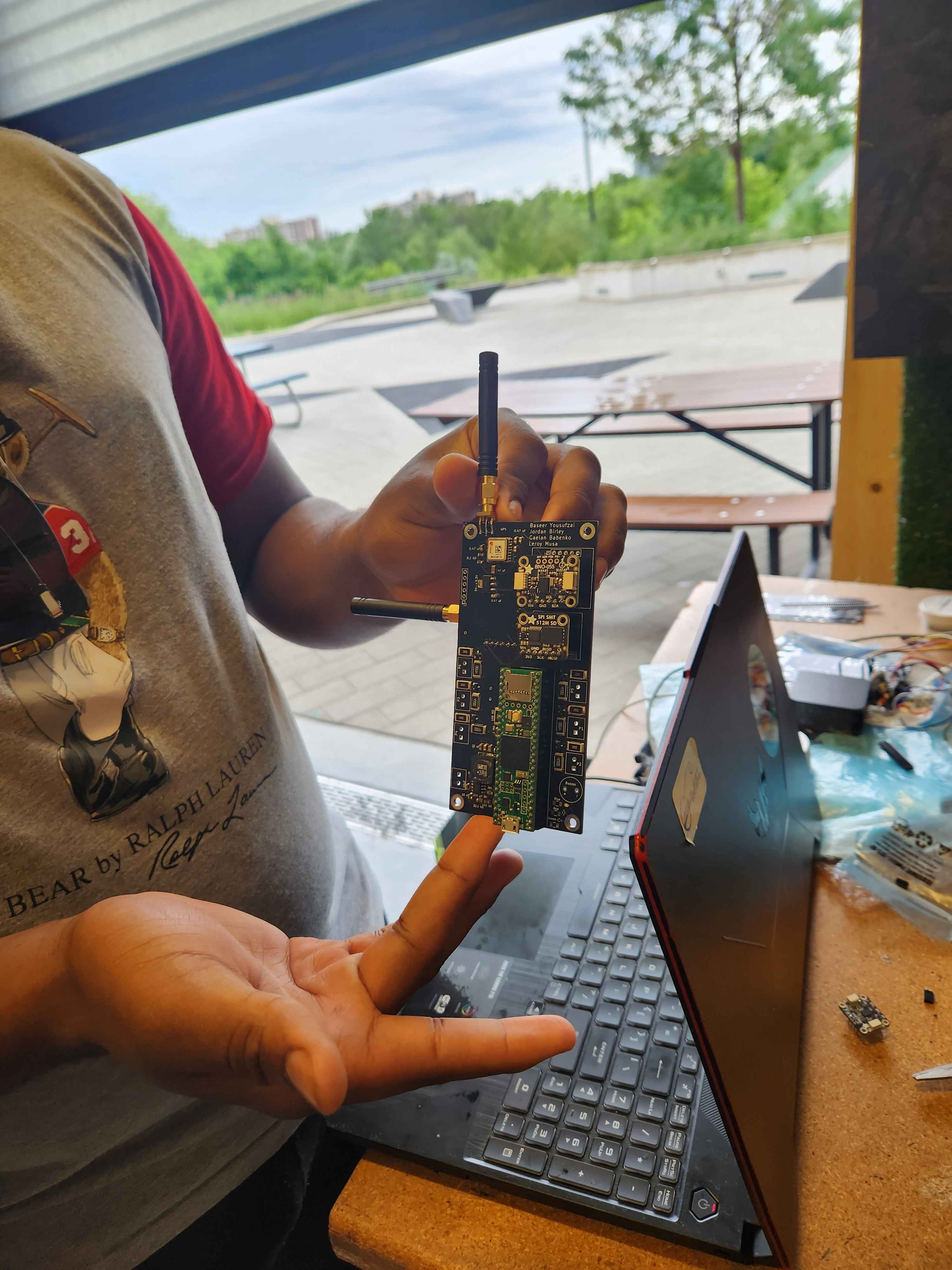
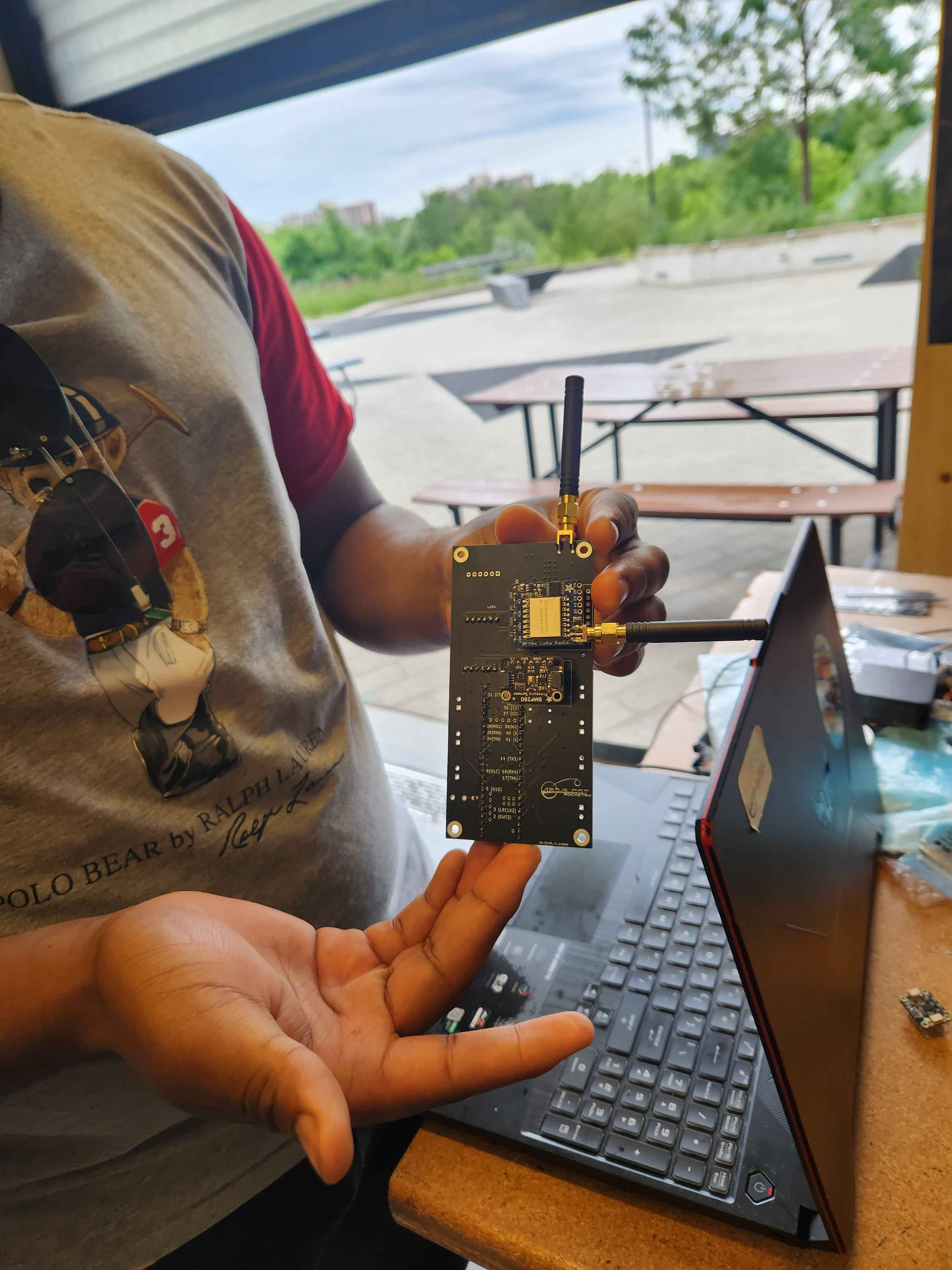
Our flight computer setup includes two unique PCBs for different rocket stages.
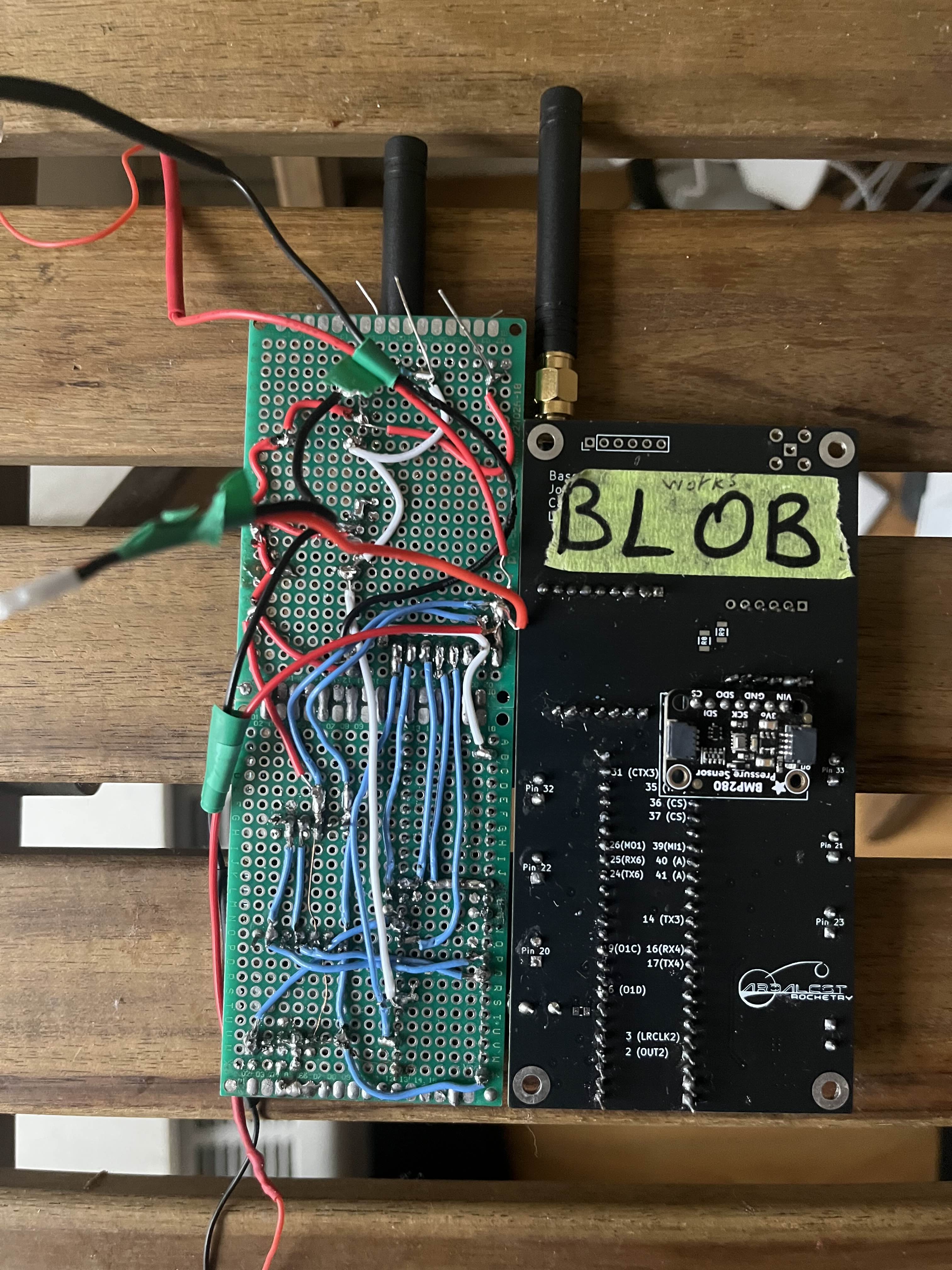
Stage 1 ("BLOB"): This PCB handles all operations for the first stage of the flight, ensuring smooth launch and initial ascent.
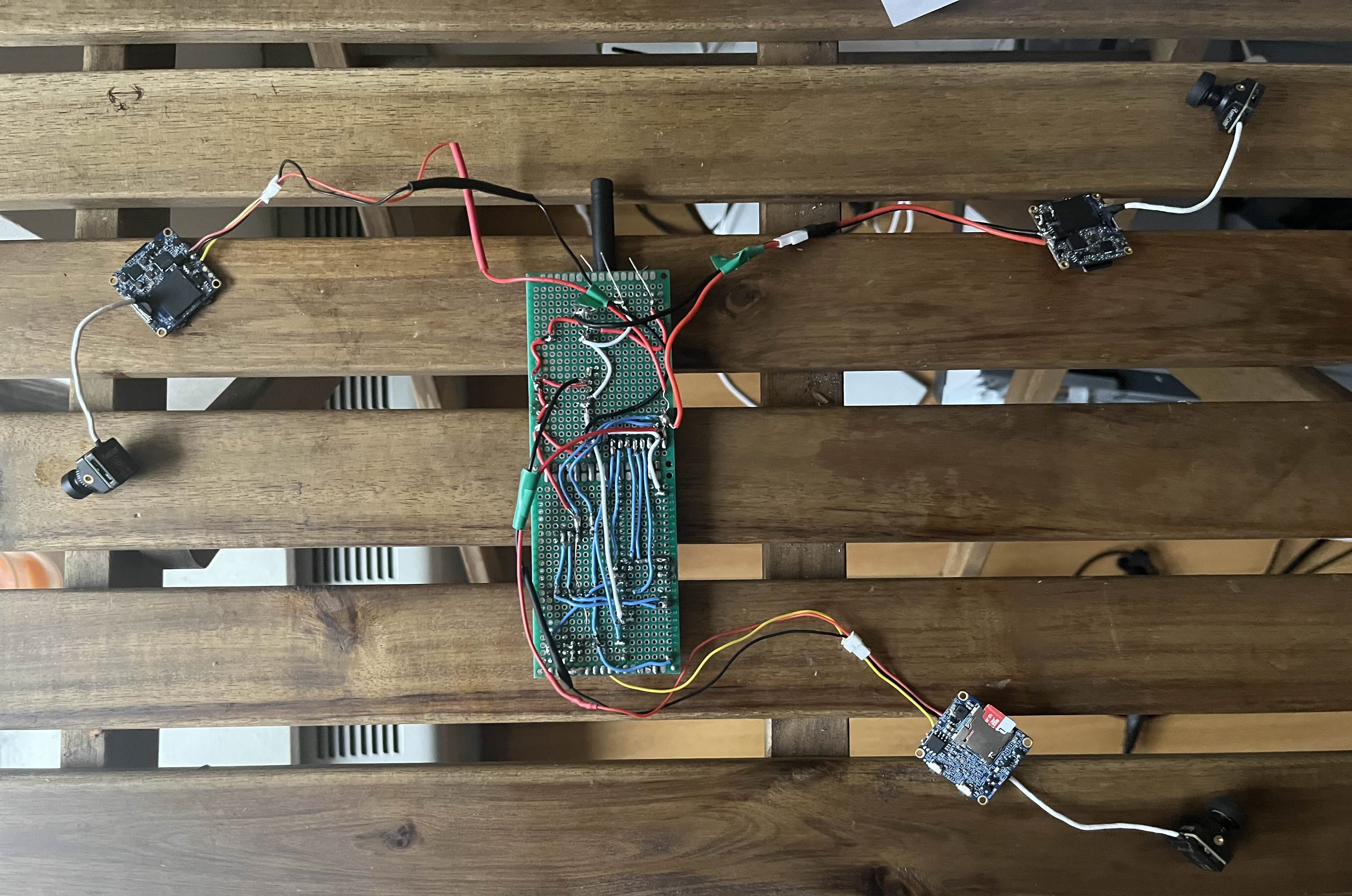
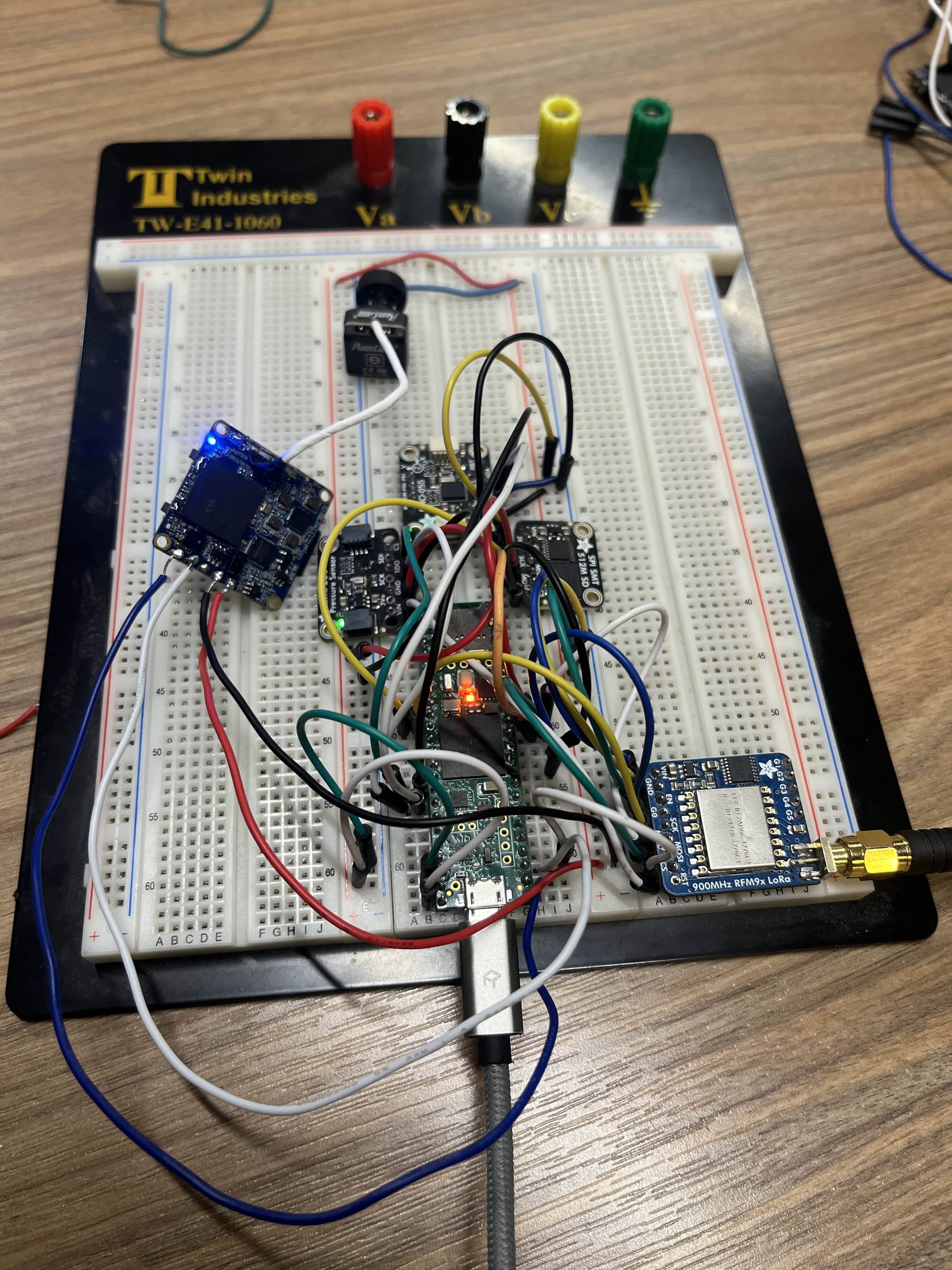
Stage 2 (Prototyping Board): This board not only manages the second stage but also controls RunCam devices for onboard video recording. Despite its prototyping nature, it functions just as effectively as the Stage 1 computer.
This dual-PCB setup ensures specialized and reliable performance throughout the entire flight.
- Microcontroller: Teensy 4.1
- Sensors:
- Altimeter: Adafruit BMP280
- IMU (Inertial Measurement Unit): Adafruit BNO055
- GPS Module: SparkFun GNSS Receiver Breakout - MAX-M10S (Qwiic)
- SD Breakout: Adafruit SPI Flash SD Card - XTSD 512 MB
- Communication: Adafruit LoRa RFM9X
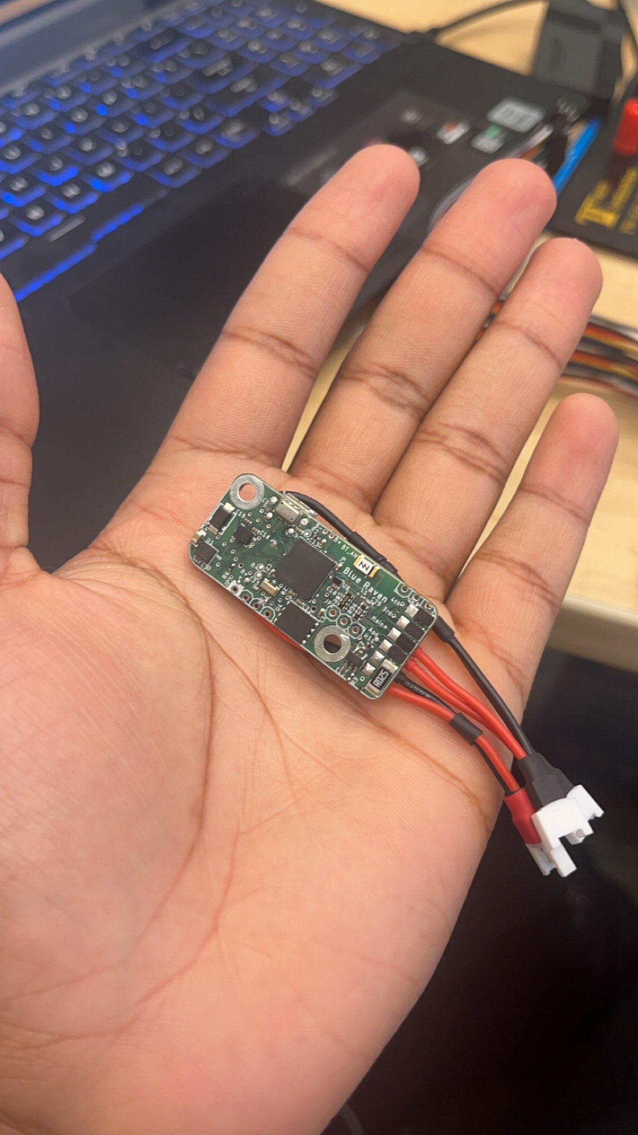
- Our COTS (Commercial Off-The-Shelf) Flight Computer: Featherweight Blue Raven (left)
- Our COTS GPS: Featherweight GPS Tracker (right)
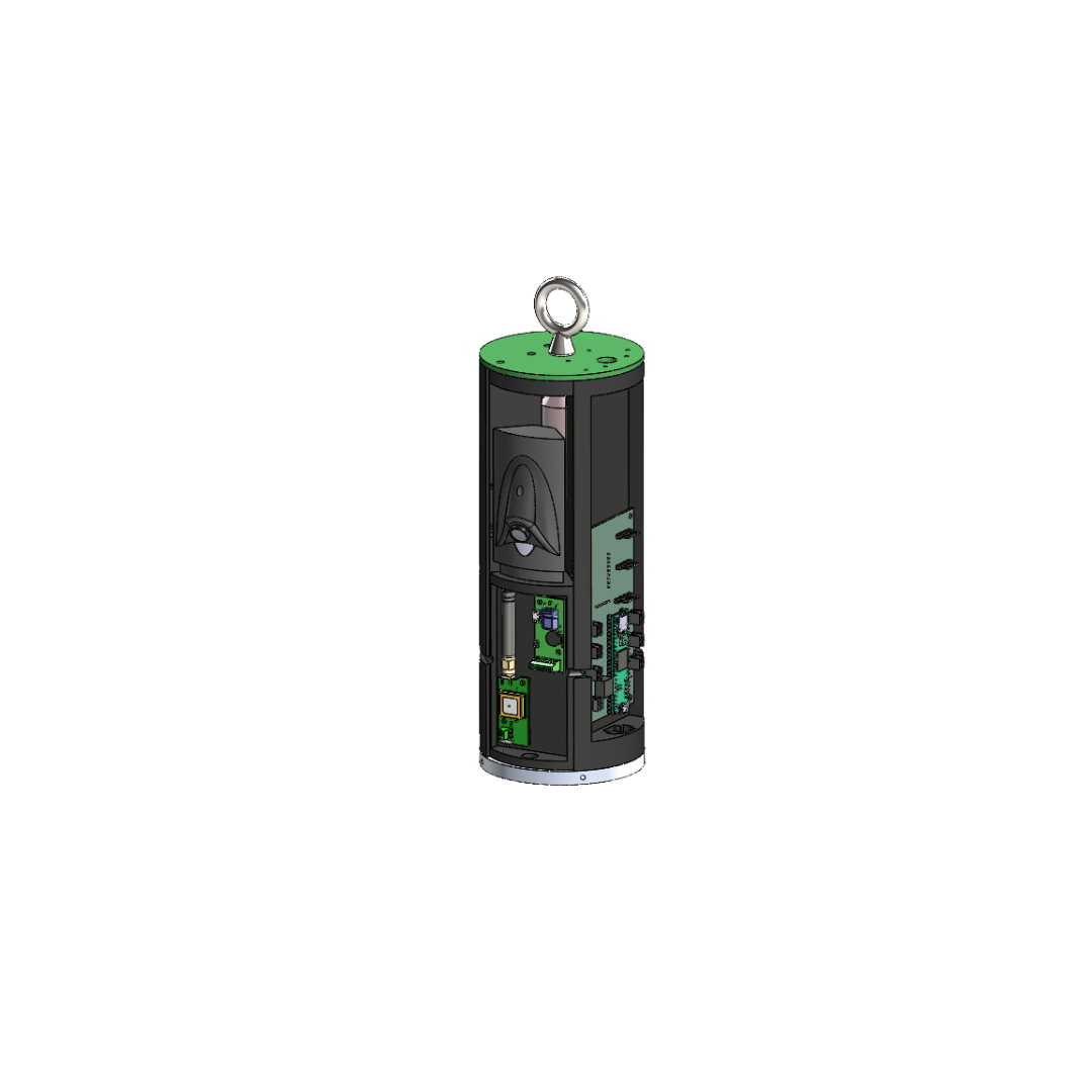
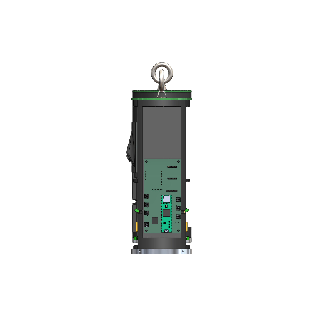
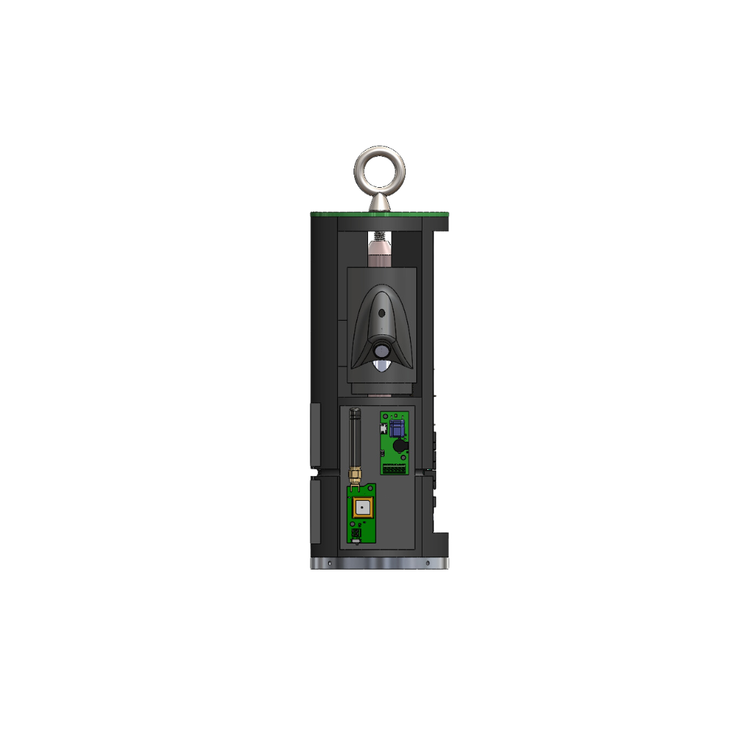
The electronics mount CAD design showcases the placement of PCBs within the rocket's fuselage. This design ensures the flight computer's and associated components' proper integration and protection.
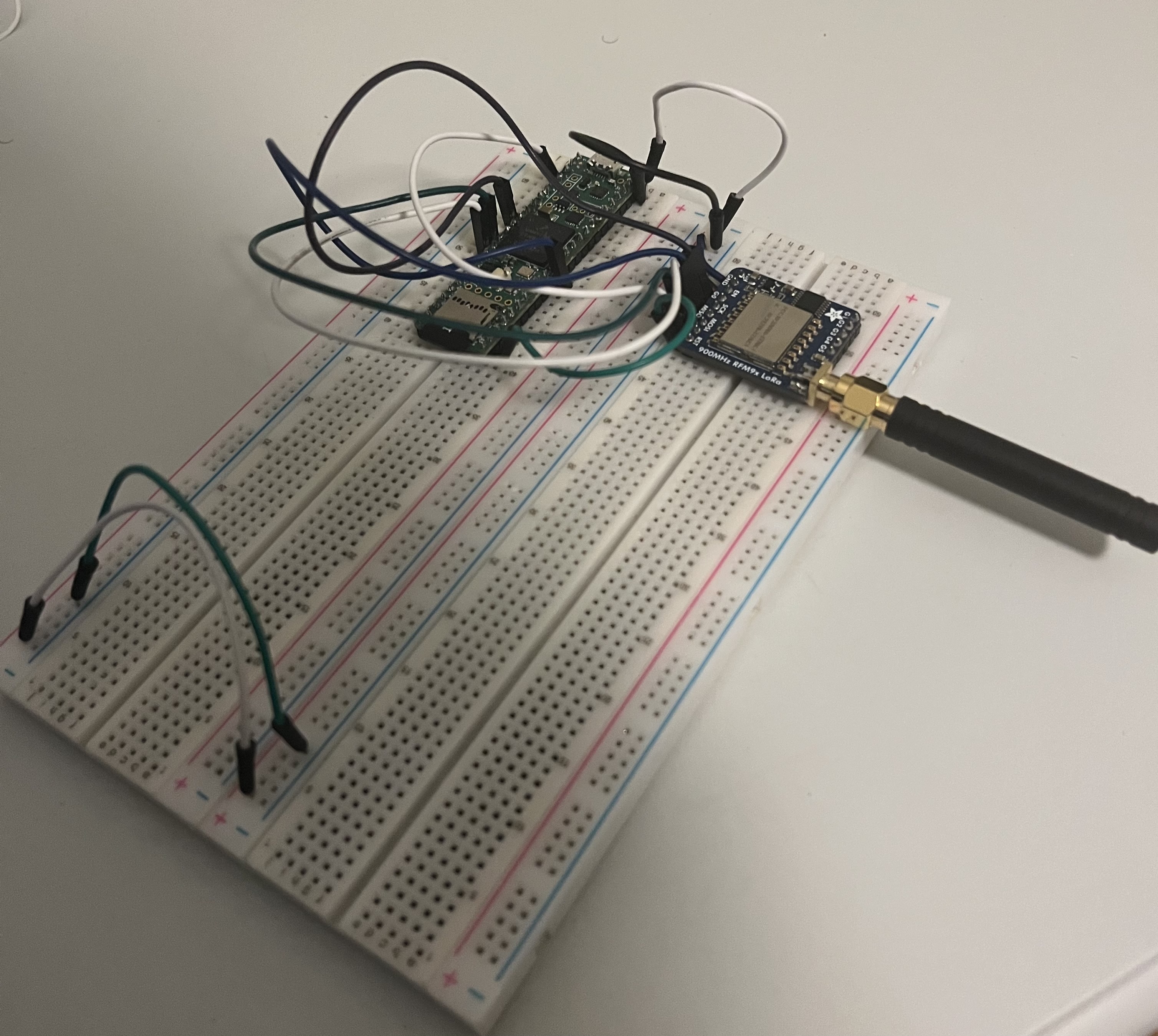
Here's an image showing my testing setup for the flight computer(left) and ground station(right):
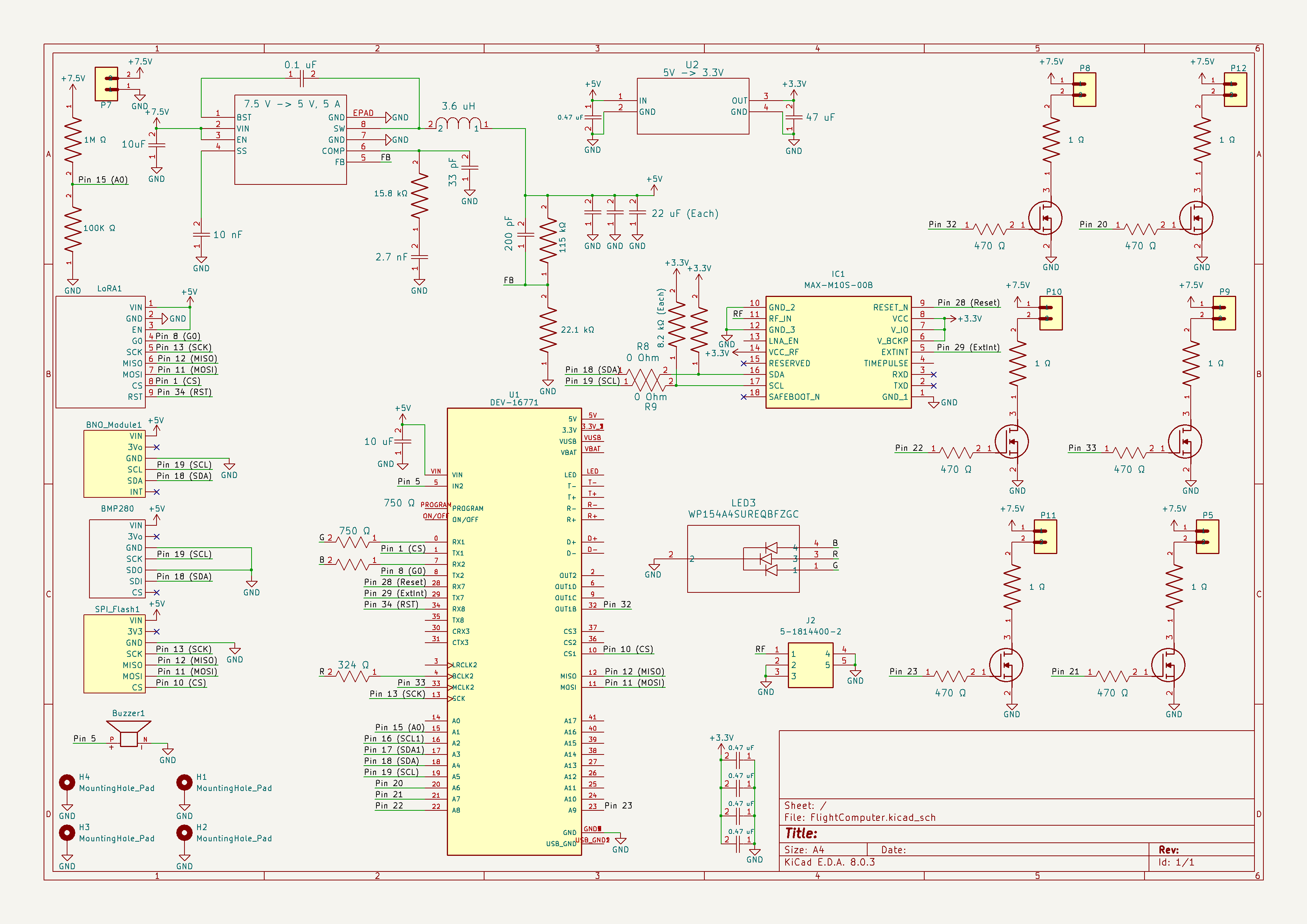
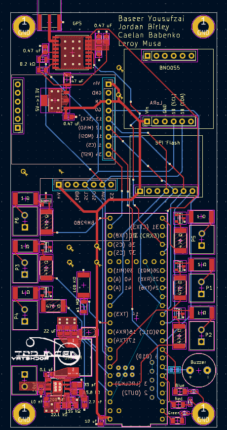
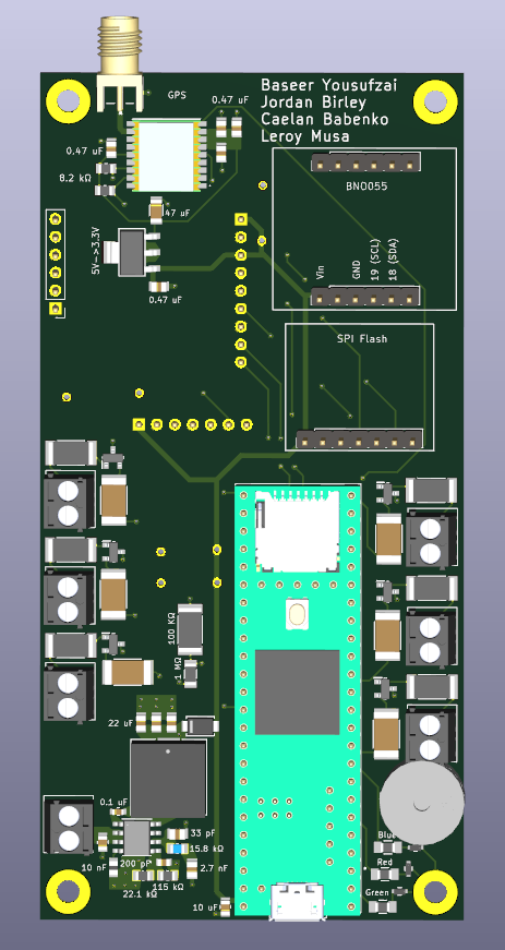
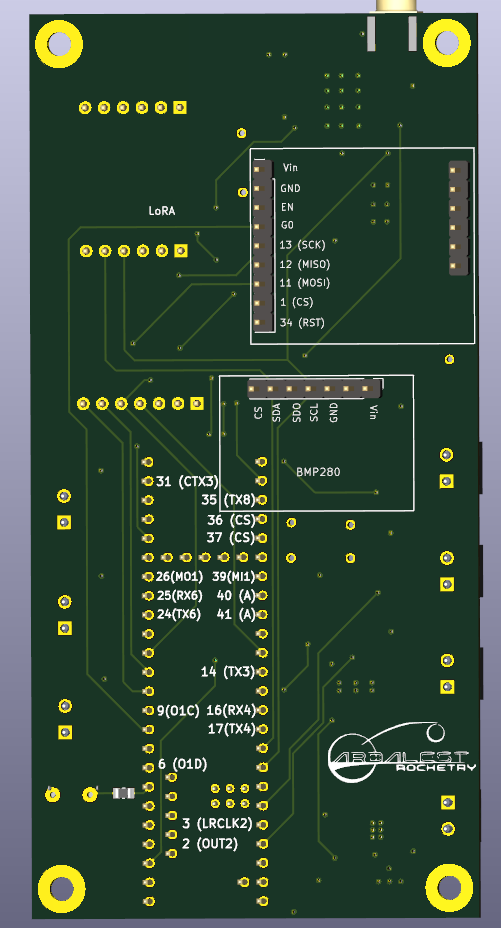
Pictures showing our current Arbalest Flight Computer schematics layout
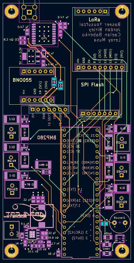
Pictures showing v1.0 of our Arbalest Flight Computer schematics layout
This table outlines the major improvements made from PCB v1.0 to PCB v2.0.
| feature | pcb v1.0 | pcb v2.0 | improvement description |
|---|---|---|---|
| layering | single-layer design | multi-layer design | enhanced routing and reduced interference |
| power supply management | basic power supply connections | advanced power routing | improved power stability and distribution |
| lora module | back right | front top right corner | better isolation from other components for improved signal quality & better placement for electronics mount |
Simple Illustration
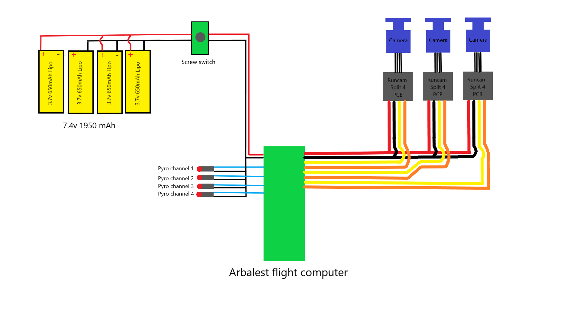
This document provides a detailed description of the Arbalest Flight Computer setup as depicted in the schematic. The system integrates four 3.7V 650mAh LiPo batteries, a screw switch, and three Runcam Split 4 cameras connected to the Arbalest Flight Computer. The flight computer controls four pyro channels specifically designed for parachute deployment.
- Arbalest Flight Computer
- 3.7V 650mAh LiPo Batteries (4x)
- Screw Switch
- Runcam Split 4 Cameras (3x)
- Pyro Channels (4x) for Parachute Deployment
The wiring diagram consists of the following connections:
- Power supply wiring from the batteries
- Activation of switch wiring
- Camera connections
- Pyro channel connections for parachute deployment
The power supply section is crucial for powering the flight computer and the connected components.
-
LiPo Batteries:
- Four 3.7V 650mAh LiPo batteries are wired in series parallel to form a 7.4V 1950mAh power pack.
- Series Connection: Two pairs of two batteries connected in series, resulting in two 7.4V packs.
- Parallel Connection: These two 7.4V packs are connected in parallel to increase the capacity to 1950mAh.
-
Wiring:
- The positive terminal of the first battery is connected to the positive terminal of the second battery.
- The negative terminal of the second battery is connected to the positive terminal of the third battery.
- The negative terminal of the third battery is connected to the positive terminal of the fourth battery.
- The negative terminal of the fourth battery is connected back to the system ground.
-
Screw Switch:
- The main power from the batteries is routed through a screw switch to control the power supply to the entire system.
- The positive wire from the battery pack connects to one terminal of the screw switch.
- The other terminal of the screw switch connects to the power input of the Arbalest Flight Computer.
The flight computer controls four pyro channels for parachute deployment.
- Connections:
- Each pyro channel (1 to 4) has two wires: one connected to the flight computer and the other to the pyro device.
- The flight computer sends a signal to activate the pyrotechnic devices through these wires.
The integration of the Arbalest Flight Computer with the LiPo batteries, screw switch, Runcam Split 4 cameras, and pyro channels provides a robust system for managing various flight operations, including parachute deployment.
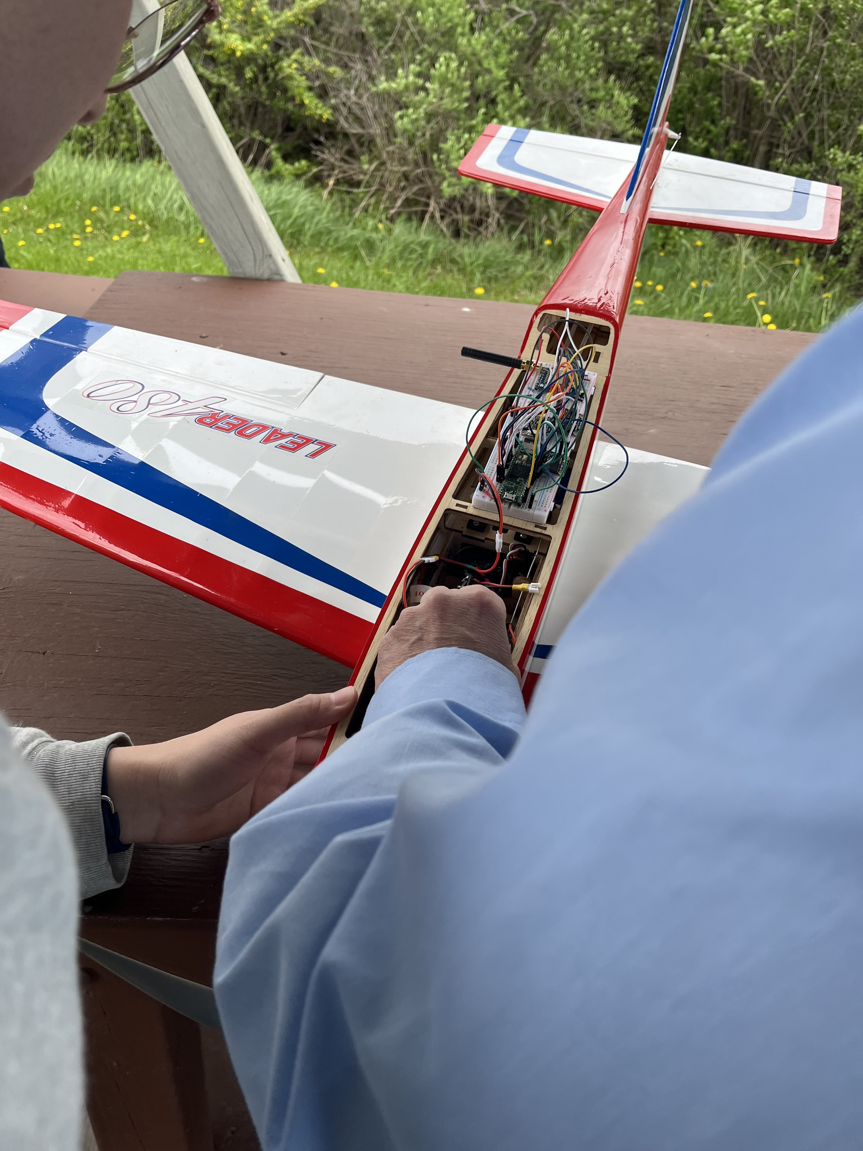
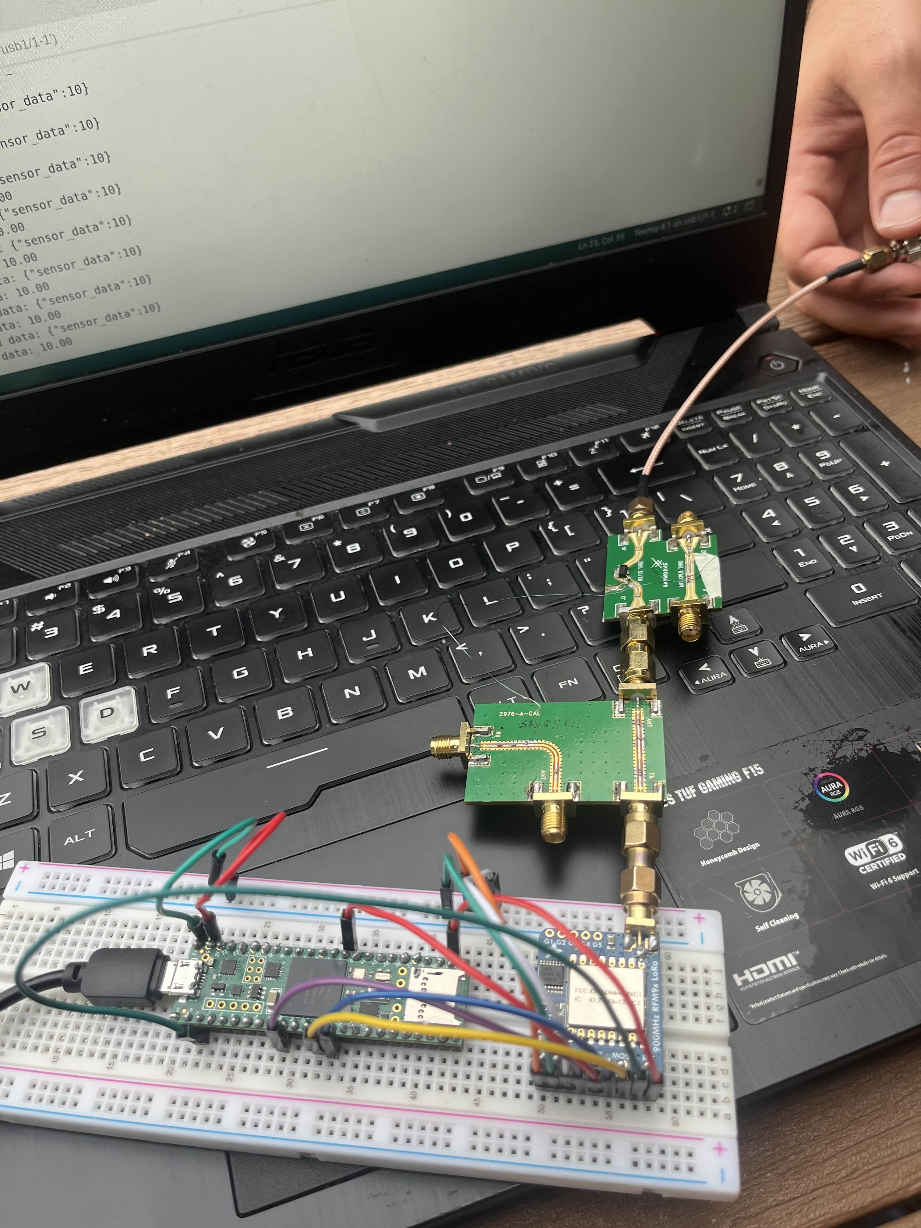
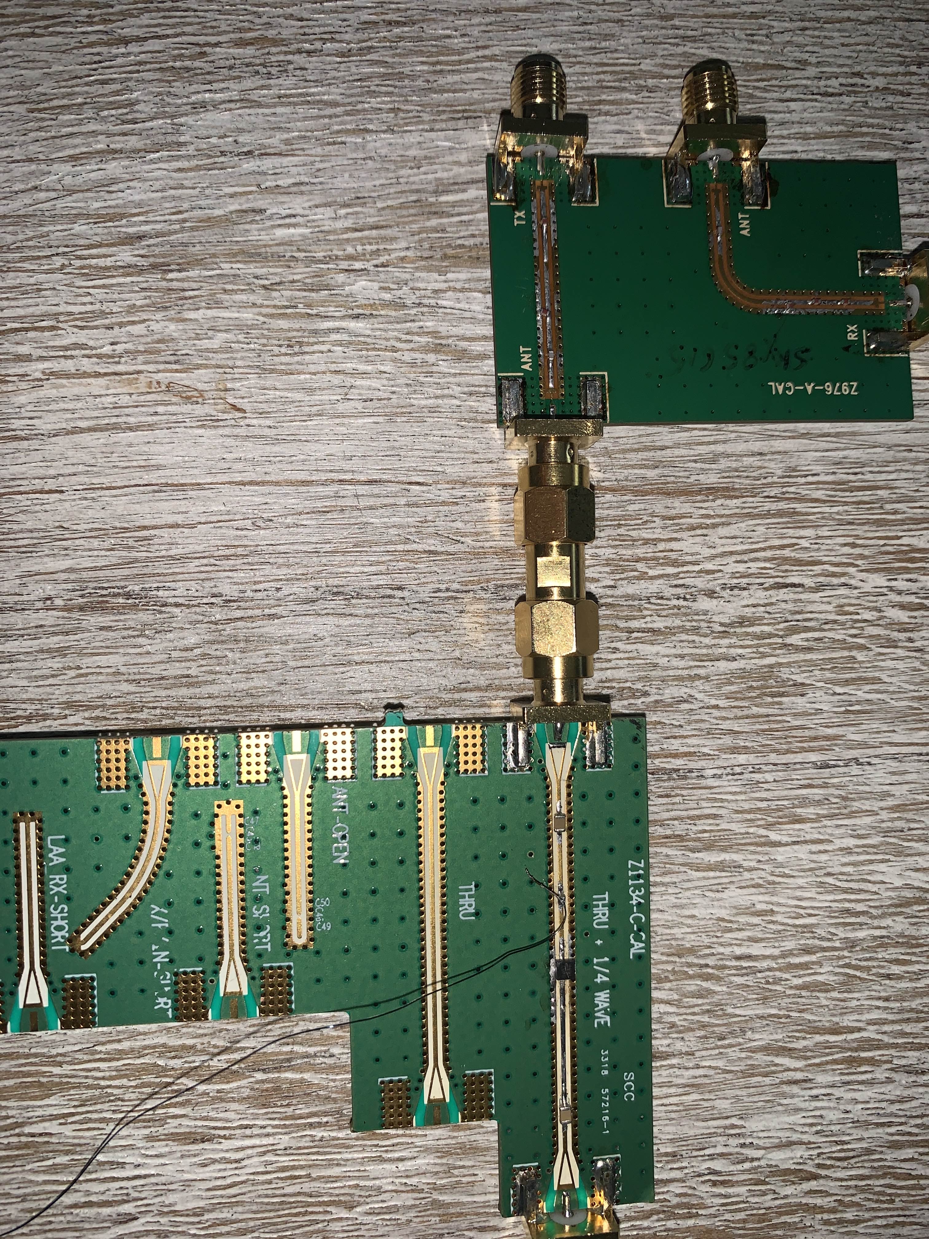
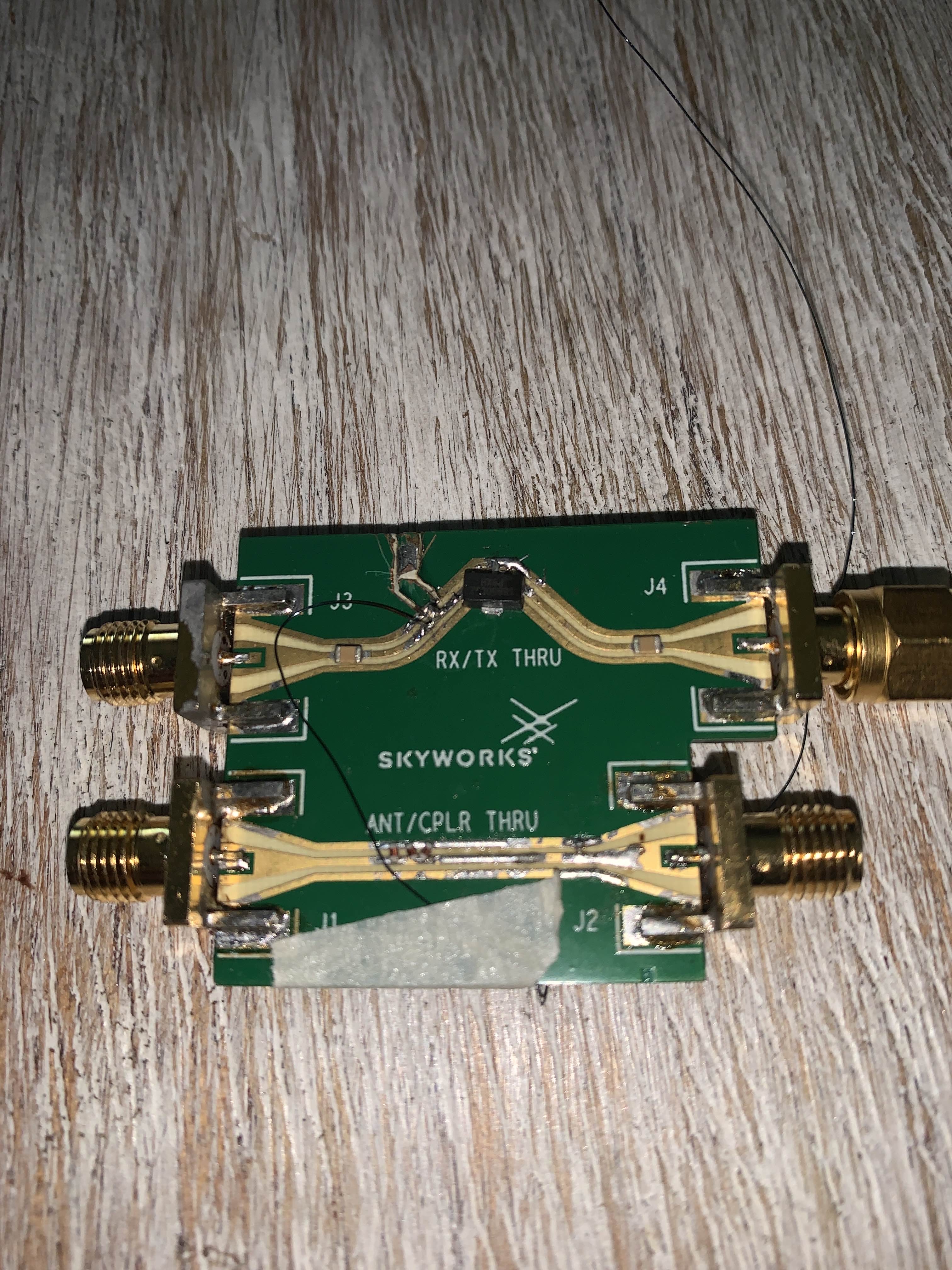
The low noise amplifiers (LNAs) are crucial components in the Arbalest flight computer's communication system. They are used to amplify weak signals received from the rocket, ensuring they are strong enough to be processed and analyzed. The following images show the setup of the LNAs connected to the Teensy 4.1 microcontroller board:
Low noise amplifiers are designed to amplify weak signals received by the antenna with minimal addition of noise. This is essential in communication systems where signal strength can be significantly reduced due to distance, atmospheric conditions, and other interference factors.
The LNA circuit shown in the images is connected to the LoRa (Long Range) communication module to improve the signal-to-noise ratio. Here’s a detailed explanation of the process:
-
Signal Reception:
- The weak signal received by the antenna is fed into the LNA. This signal is typically very weak and can be easily lost in the noise.
-
Amplification:
- The LNA amplifies the weak signal. The primary goal is to increase the signal strength without adding significant noise. This is achieved through the careful design of the amplifier circuit, using high-quality components that contribute minimal noise.
-
Filtering:
- After amplification, the signal may pass through a filter to remove unwanted frequencies or noise that might have been introduced during amplification. This ensures that only the desired signal is sent to the next stage of the communication system.
-
Enhanced Signal:
- The enhanced signal, now much stronger and clearer, is fed into the LoRa module. The LoRa module can now process this signal more effectively, providing reliable communication over long distances.
The LoRa communication module is known for its ability to transmit data over long distances with low power consumption. By connecting the output of the LNA to the LoRa module, we achieve the following benefits:
-
Increased Range:
- The amplified signal can travel greater distances without degradation, improving the overall range of the communication system.
-
Improved Signal Quality:
- The higher signal-to-noise ratio achieved through amplification and filtering results in better signal quality, reducing the likelihood of errors in data transmission.
-
Enhanced Reliability:
- With stronger and clearer signals, the communication link becomes more reliable, which is critical for mission success in rocketry.
- Leroy Musa - Author & Maintainer
