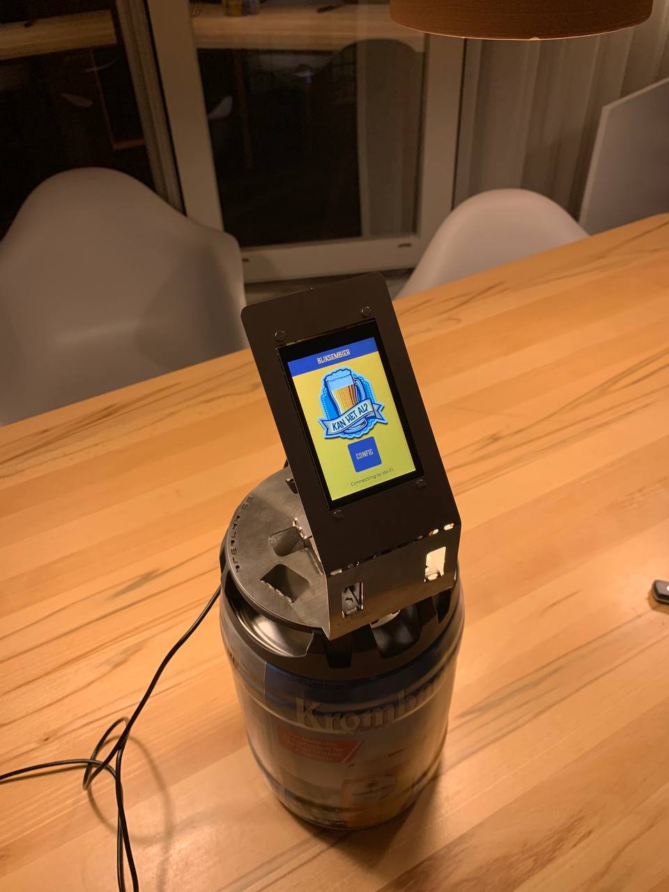
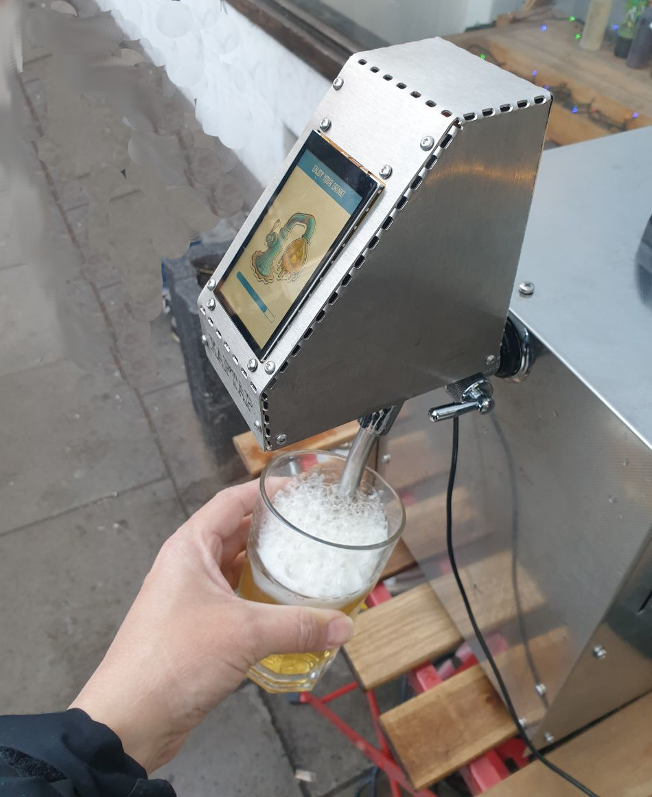
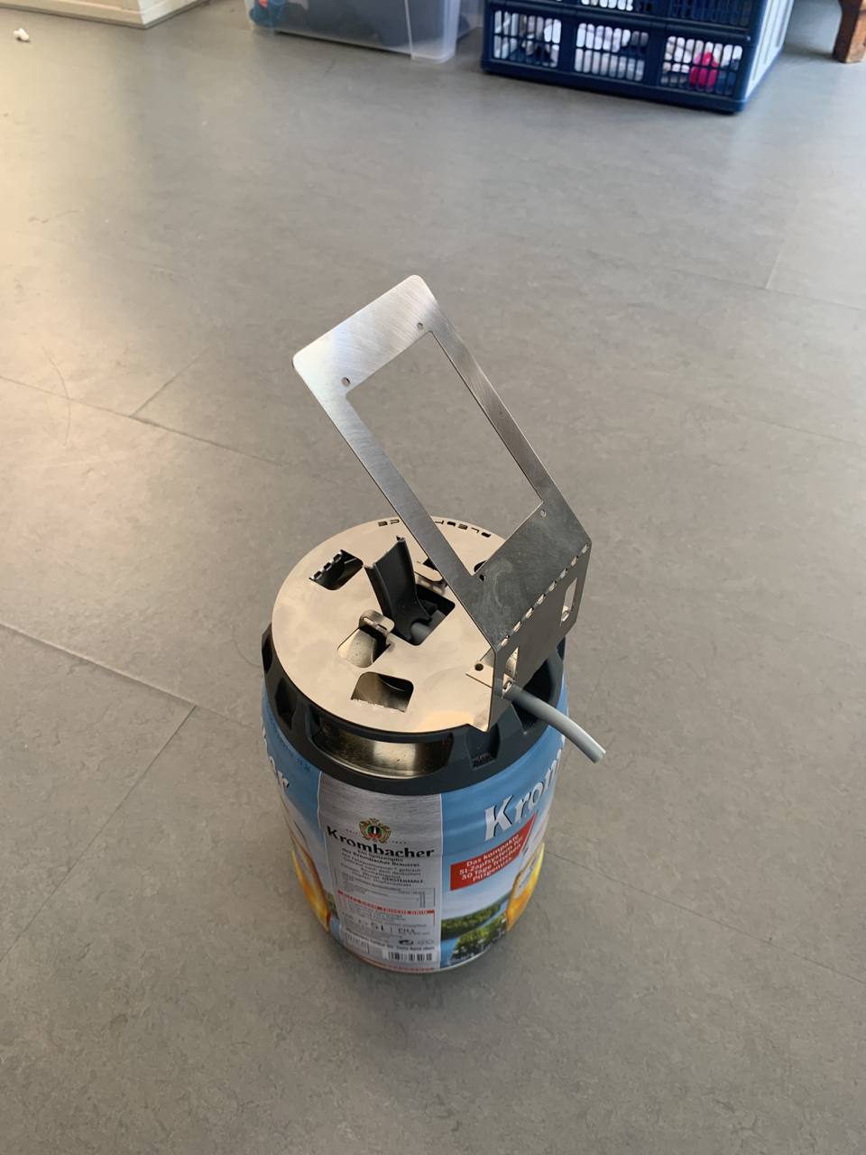
BliksemBier is a beertap that accepts Bitcoin through Lightning payments. Support for NFC card payments is also include. BliksemBier consists of two components: an LNbits (https://github.com/lnbits/lnbits) extension and firmware for an ESP32-based smart display (made by Sunton). The firmware for the tap is created in such a way that can be used for different beertap types. For 5L draught kegs to professional beertaps. The following pictures illustrate some of the applications of BliksemBier.
If you want to obtain or create such a beertap, you can buy one or create one yourself (see the build instructions for more details). All components, except for the metal sheet, are readily available. The design for the metal sheet is available here. This should be laser cut out of a 1mm - 1.5mm stainless steel sheet. As that can be quite expensive for a few items, you can also obtain one from me. Contact me for details.
If you want to contact me directly, send an e-mail to bliksembier@meulenhoff.org.
You can also join the Telegram group (https://t.me/+NLCoqbPB_ro1NzRk).
To get the beertap up and running, take the following steps:
- Make sure your LNbits server has the BliksemBier extension installed. If not contact the administrator of your LNbits server and ask to install the BliksemBier extension from the following source:
https://lnbits.meulenhoff.org/extensions/extensions.json - In LNbits, add the BliksemBier extension to your wallet.
- Select the 'BliksemBier' extension and clik the 'New Device' button.
- Configure the device with a title, wallet, currency and at least one switch (up to three switches are supported). If unsure, no problem, you can change the configuration anytime.
- The duration is the amount of milliseconds, the tap is switched on.
- The Label button is displayed on the tap. For instance 'SMALL' or 'LARGE'. Currently, only a limited subset of characters is support (CAPS ONLY).
- Click 'CREATE DEVICE' and record the ID of the LNURLdevice (8 charachters).
Now move over to the beertap itself. If you need to flash (new) firmware to the device, go to step 12.
- Power on the beertap and click the 'Config' button.
- Enter the PIN (the initial PIN is 123456)
- Configure SSID and Secret to connect the tap to a Wi-Fi network.
- Make sure that LNbits host is set to: lnbits.meulenhoff.org
- Set 'Device ID' to the ID of the LNURL device (from step 6).
- Click connect.
If all went as planned, the status says: Wi-Fi connected, Configuration loaded, WebSocket connected and 'Ready to Serve!'. You can click on one of the buttons and scan the QR code.
The flash new firmware on the device, make sure you are using LNbits with the Chrome (or Edge) browser.
- Connect the Micro USB port of the ESP32 to your computer.
- In the BliksemBier extension, select the correct ESP32 board and click the flash button to start the flashing process.
- In some cases, flashing only works the second time.
- The 'Boot button' that is mentioned during flashing is typically not required. However, the boot button is located on the back of the ESP32 device (next to the reset button). Pressing both at the same time (while having the ESP32 connected to your computer) usually does the trick.
A list of components required to build a BliksemBier tap for 5L draught kegs:
- Sunton ESP32 Capacitive touch display 3.5 inch (https://aliexpress.com/item/1005004632953455.html)
- One MG995 servo
- 2 JST 1.25 connectors
- A stainless sheet fixture
- USB-C connector for power (https://www.aliexpress.com/item/1005005137763022.html)
- USB 5V power source of at least 2A @ 5V
- Some screws and wiring:
- 4 M3 bolts (20 mm)
- 4 4mm spacers
- 8 M3 nuts
- 1 M4 bolt (15 mm)
- 1 M4 Locking nut
- A box for the backside (I used a Strapubox 2515)
- soldering utensils and a small piece of heat shrink
BliksemBier also supports NFC payments with a Boltcard compatible smartcard. If you want to enable that, you need the following additional components:
- 2 JST SH / STEMMA QT cables. Make sure the cable is long enough to place the NFC reader where you want.
- 1 JST GH 4-pin cable with a single connector (or just cut off the connector)
- 1 PN532 NFC reader module (https://www.kiwi-electronics.com/nl/pn532-nfc-rfid-breakout-board-3622)
- 1 Adafruit Attiny 1616 Seesaw breakout module (https://www.adafruit.com/product/5690)
- Isolation tap or shrink tube (to isolate the Seesaw module)
Both the ESP32 and the Servo are powered from the 5V source. As the servo is quite strong, a weak power source will result in glitches of the display. Make sure your power source is strong enough. Also it is important not to pass the current for the servo through the ESP32. This means that both the ESP32 and the Servo are directly powered from the same 5V power source. Use the following guidelines to connect everything.
- The 5V power connects to the VIN of the ESP32 and the power input of the servo (middle cable)
- The GND of the power input connects to the GND of the ESP32 and the GND of the servo (black cable)
- Port 21 of the ESP32 connects to the signal input of the servo (Yellow cable).
- Use the JST connectors to connect both power and signal (PIN 21).
Connecting everything together may require some soldering and heat shrink. A closeup of the backside should like similar to the following.
The box for the backside of the tap is a converted strapubox that comes in two identical covers. I cut of the rims of the box, made a hole for the USBC connector and drilled four holes to mount the cover on the same bolts that mount the display to the metal fixture.
BliksemBier also supports NFC payments with a BoltCard (NTAG 424). Go the PlebTag Shop if you want to buy these cards wth a nice design. As the Sunton Smartdisplay is a bit limited on IO, both the NFC reader and the servo are connected through I2C.
The PN532 NFC reader module is connected through I2C with a JST SH / STEMMA QT connector. First set the switches on the PN532 to the position that I2C mode is enabled. Also, depending on your application, make sure the cable is long enough so that the NFC reader can be placed where you want. The following picture shows which cable must be soldered to which port.
When finished, the module should look like this:
Note that the cable is now a lot longer (my initial cable was way too short). The connector can be plugged into one end of the Seesaw module.
The purpose of the Seesaw module is to pass through the I2C bus to the PN532 and more importantly, provide an additional PWM port to drive the servo.
The yellow cable that (see standard build instructions) that provides the servo signal, is soldered to port 1 of the Seesaw module.
The Seesaw module is connected to the 'Temperature/Humidity Interface' of the display. That is the conector with the pins: 3.3V, IO21, IO22, GND. This connector is of a JST GH type, which means that a cable must be made that converts JST GH to JST SH. A picture of both these cable types is shown below:
The mapping of the pins is provided in the following picture:
Note that the color of the JST GH cable is not correct. It is just the cable I got and I did not change its configuration. Put a piece of shrink tube on each cable before soldering. The final result shoul like similar like this:
The cable can now be connected to the display and the other end to the Seesaw module.
No connected everything together, the PN532 module to the Seesaw module and the Seesaw module to the smartdisplay. Provide electrical isolation for the Seesaw module so it does not create a short circuit. The final assembly should look similar to this:
And a picture of the complete assembly with the Seesaw module isolated and fixed to the casing.
To compile the project from within Visual Studio Code using platform.io, take the following steps:
- Install Visual Studio Code. Download from https://code.visualstudio.com/. If Git is not yet installed on your system, you need to install that as well.
- Install the Platform IO extension. Open the Extension Manager (click the wheel icon at the bottom of the bar and the left and select Extensions). Search for PlatformIO, and click 'Install'.
- In Visual Studio code, open the command palette (Ctrl-Shift-P) and type 'gitcl'.
- When prompted for the repository URL, enter the URL of this repository:
https://github.com/pieterjm/BliksemBier.git - Select a local directrory where to store the repository and open the repository.
- To compile, click the checkmark icon in the blue bar at the bottom to compile the repository. This may take a while as external libraries have to be loaded.
- Connect the device to USB port and click the '>' button in the blue bar at the bottom to compile and flash the firmware.
- After compilation and firmware flashing is succesful, the device should restart as a fresh Btap.
To compile the project using platformio core only, take the following steps
- Install platformio core by following the instructions here: https://docs.platformio.org/en/stable/core/installation/methods/installer-script.html
- Clone the repository with the following command
git clone https://github.com/pieterjm/BliksemBier.git - Compile and upload
cd BliksemBier
platformio run --target upload


