This project treats the development of an IoT smart city using Arduino. The smart city will be equipped with the following functionalities:
- Smart lighting;
- Smart parking;
- Air quality monitoring;
- Flood management;
Each feature will be explained in the dedicated sections.
- Getting started
- Materials used in the project
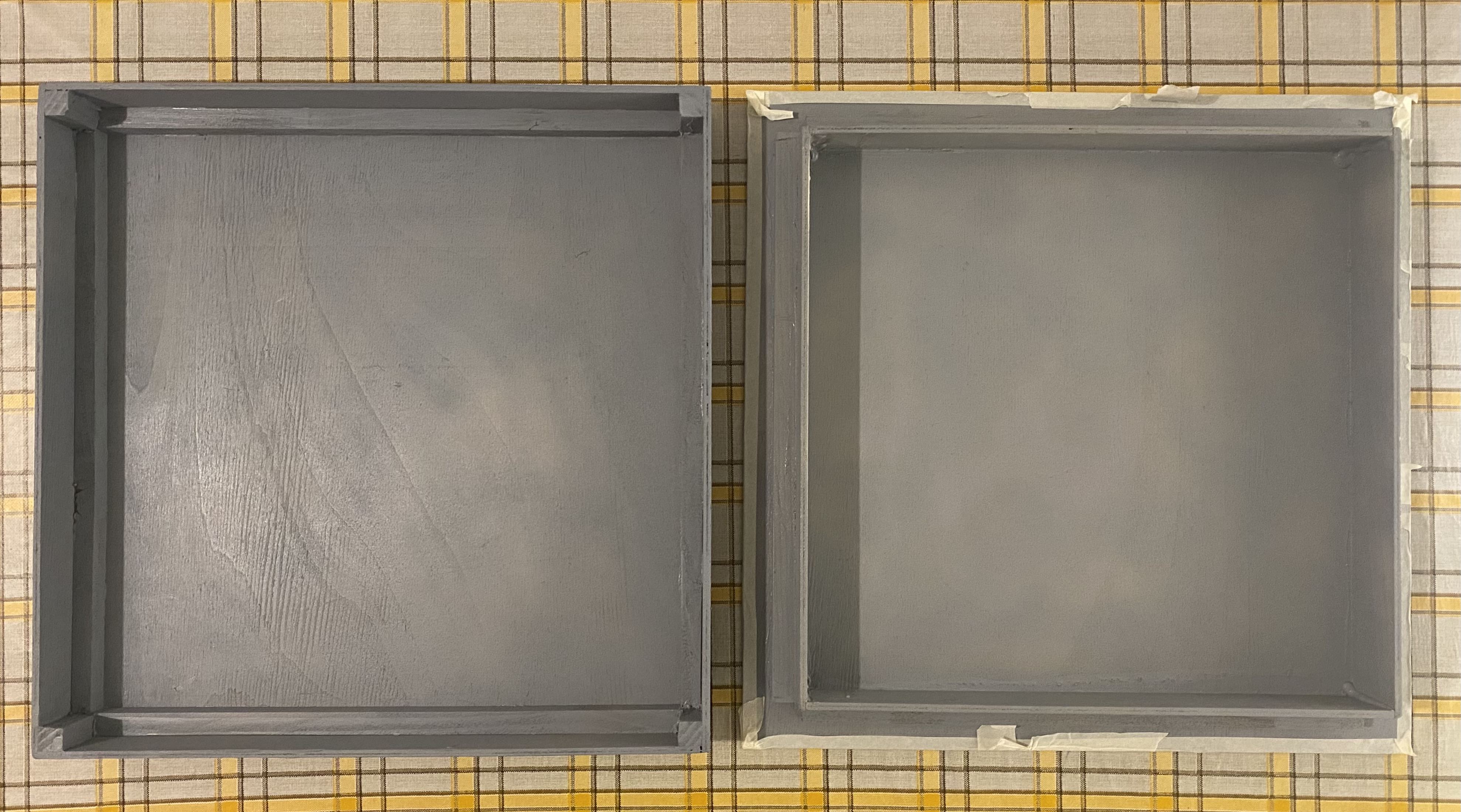
- Step 1: Box creation
- Step 2: Single sections wiring and code
- Step 3: Create MQTT communication with Web Application
- Step 4: Place all devices on the box model
Since our smart sensors can communicate, using MQTT, with a web-application built with Node-Red, we need to setup the enviroment. In our project we used a RaspberryPi 3 to host the MQTT broker and Node-Red, but it's possible also to host them on your pc.
As first step you need to do the initial setup for the RaspberryPi.
- Insert a microSD card / reader into your computer.
- Download and install the official Raspberry Pi Imager.
- Run the Imager program, choose the OS as Raspberry Pi OS (32-bit), choose the SD card and write the image.
Install the MQTT broker.
apt-get install mosquitto
To modify the config file use:
sudo /etc/init.d/mosquitto stop
sudo nano /etc/mosquitto/mosquitto.conf
To autostart on boot use:
sudo systemctl enable mosquitto
sudo systemctl start mosquitto
First, you need to check that npm is able to fetch and build any binary modules it needs to install.
sudo apt install build-essential git curl
With the following command you can install Node.js, npm and Node-RED.
bash <(curl -sL https://raw.githubusercontent.com/node-red/linux-installers/master/deb/update-nodejs-and-nodered)
To set the autostart on boot use:
sudo systemctl enable nodered.service
Now you can access to http://localhost:1880 and you need to install the node-red-dashboard palette. Import the flows.json file.
You also need to set the static images. To do that go in the ./node-red folder, and modify the file settings.js with the following line:
...
    // When httpAdminRoot is used to move the UI to a different root path, the
    // following property can be used to identify a directory of static content
    // that should be served at http://localhost:1880/.
    // httpStatic: '/home/nol/node-red-static/',
    httpStatic: 'home/{{userName}}/.node-red/static'
...
After, create the static folder in home/{{userName}}/.node-red, putting inside all the pictures inside the folder dashboard_images.
Finally restart your node-red.
Install the MQTT broker and modify the file mosquitto.conf inserting the following lines to allow remote access:
listener 1885
allow_anonymous true
- Download and install Node.js;
- To ensure the correct installation run in the terminal:
node --version && npm –version
- Install Node-RED using:
npm install -g --unsafe-perm node-red
- Execute:
node-red
- Now you can access to
http://localhost:1880and you need to install thenode-red-dashboardpalette. NB: you need to import the flow and set the static images.
-
Box:
- 4mm thick plywood (1m x 1m);
- 1.5cm x 1.5cm bar (3.2m);
- Gray acrylic spray;
-
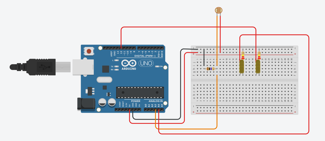
Smart Lighting:
- Light Sensor (Photoresistor);
- Resistor 10k ohm;
- Resistor 220 ohm (2x);
- Yellow LED 5mm (6x);
- Street lamp 3D Model (50% scaled);
- Solder Iron;
-
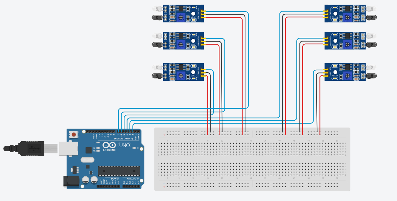
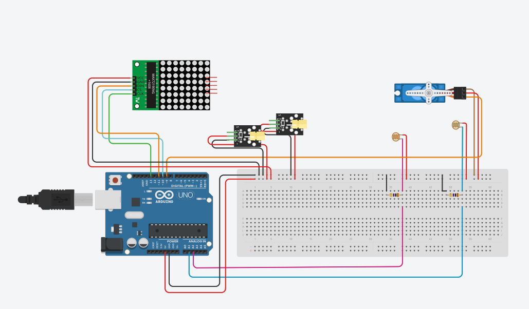
Smart Parking:
- IR Infrared Obstacle Avoidance Sensor Module (6x);
- Light Sensor (Photoresistor) (2x);
- Resistor 10k ohm (2x);
- KY-008 Laser Module (2x);
- Servo micro TowerPro sg90 9g;
- 8x8 Dot Led Matrix Module;
-
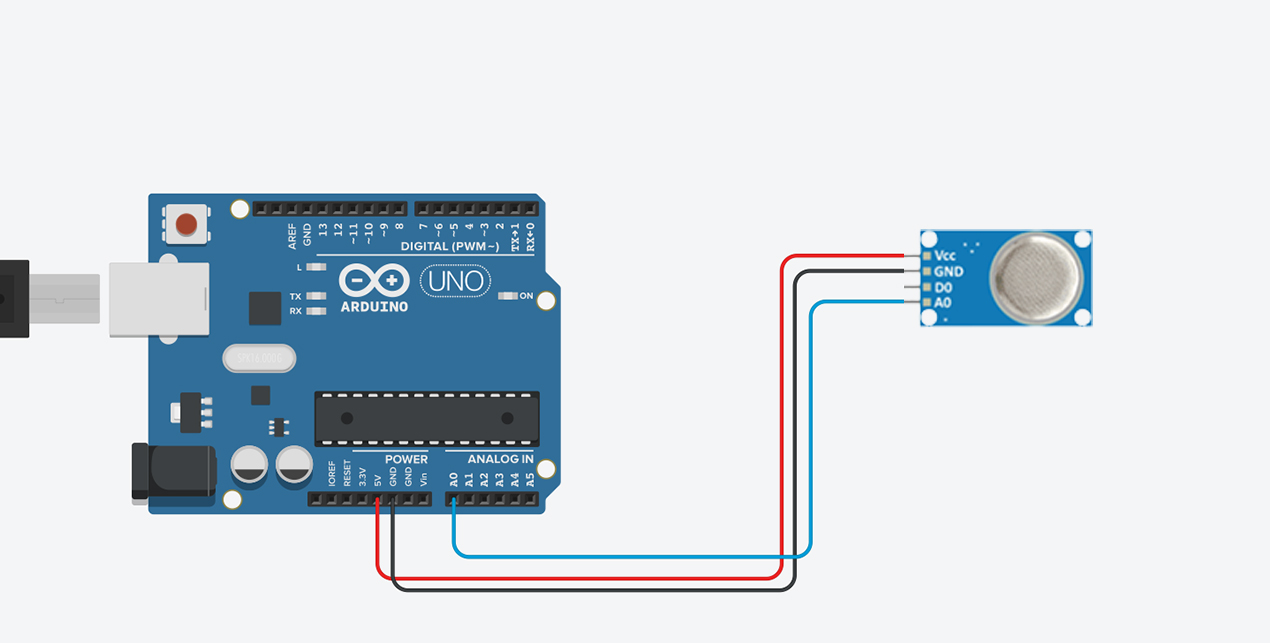
Air Quality Monitoring:
- MQ2 Air Quality Sensor;
-
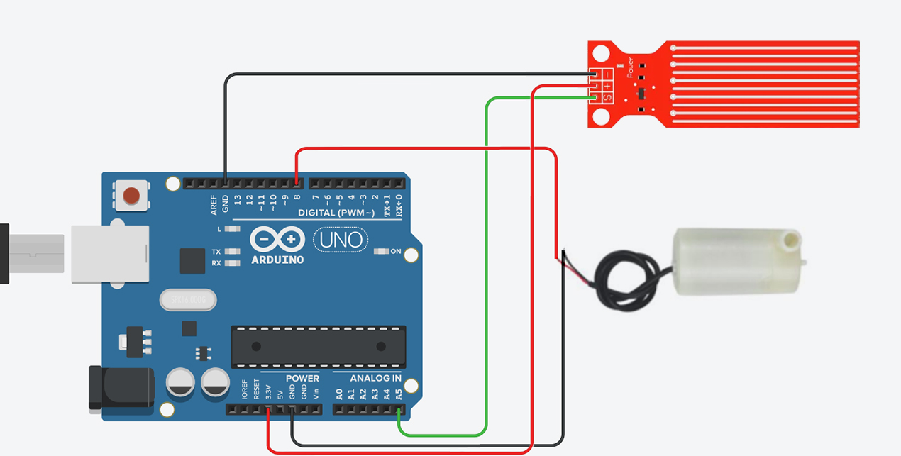
Flood management:
- Water Sensor;
- Water pump 5V;
The code for this section is available in the folder single_sections_code/StreetLights.
The various connections for building the smart parking lot have been divided for illustration purposes only. The first image shows the components needed to detect the presence of a car in each lot. The second image shows the components needed for entry and exit in the parking lot equipped with a bar and how available and occupied spaces are shown.
The code for this section is available in the folders single_sections_code/Parking and single_sections_code/ParkingBar.
To use this code you need to install these libraries:
The code for this section is available in the folder single_sections_code/AirQuality.
The code for this section is available in the folder single_sections_code/FloodManagement.
As first step, we estabilished all the topics for the communication:
topic/street_lightstopic/air_qualitytopic/flood_managementtopic/parking
Next, we specified the message format as follows:
STREET LIGHTS:

--- {lights_status: value},

where "value" can be "0" if the lights are OFF, and "1" if they are ON.
AIR QUALITY MONITORING:

--- {air_quality_status: value},

where "value" can be "0" if the air quality is GOOD, and "1" if it is BAD.
FLOOD MANAGEMENT:

--- {flood_status: value},

where "value" is the water level.
PARKING:

--- {free: value, slot1: status, slot2: status, slot3: status, slot4: status, slot5: status, slot6: status},

where "value" is the number of free slots and "status" that can be "1" if the slot is free, "0" if it is busy.
To publish messages using Arduino we need to install the following libraries:
All the scripts to send messages are in the folder single_sections_code_mqtt.
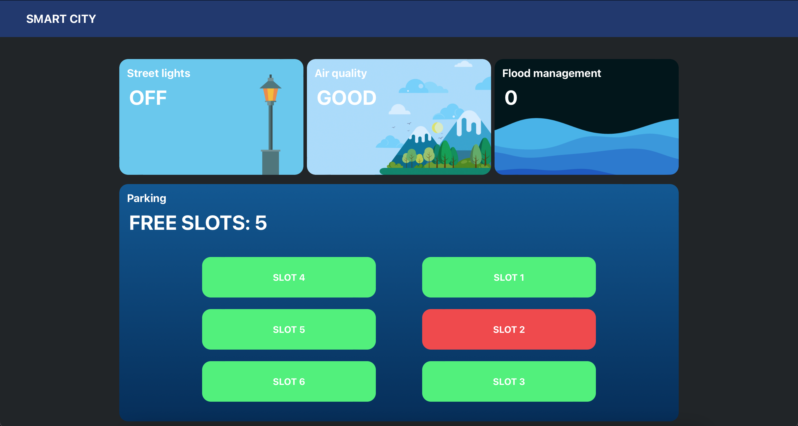
To built the Web Application to receive and display messages, we used Node Red. The flow is flows.json. The node configuration on Node Red consists of 5 nodes that receive messages from Arduino and are displayed in custom templates. The "template" node named custom_template was used to customize the style of the dashboard.
The final result is showed in the next picture.
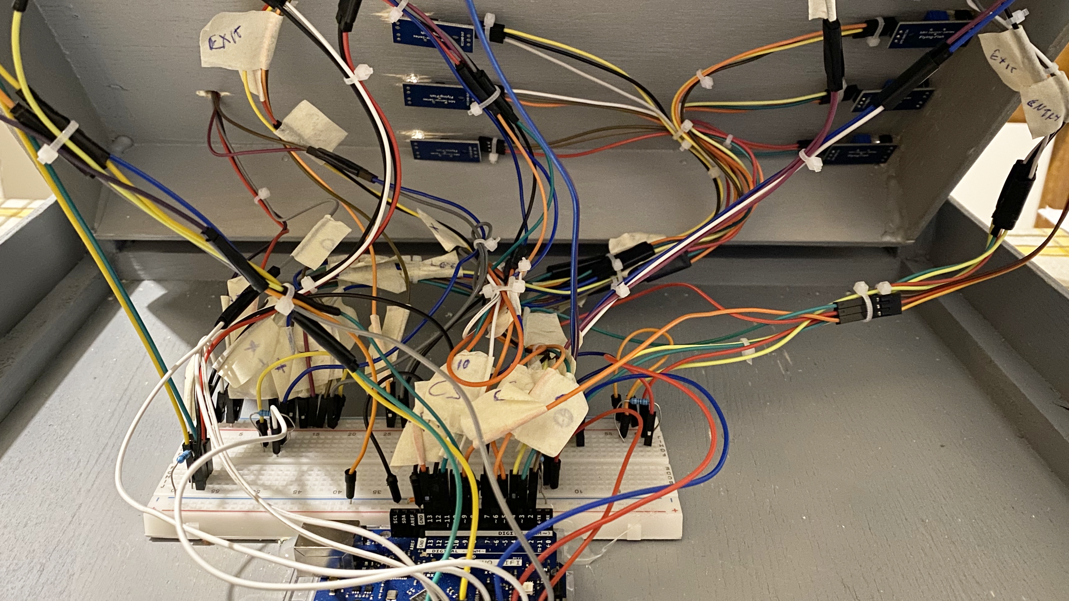
We connected each sensor to an Arduino WIFI REV 2. The full code is in MainProgram.
Street lights use a photoresistor to capture the amount of light. At sunset the lights will turn on.
Lights.mp4
When the car attempts to enter the parking area, the bar will only open if there are spaces available. When the car occupies a certain slot it will be shown on the LED matrix which slot has been occupied. During the procedure all information will be shown on the dashboard.
parking.mp4
Air.mp4
When the water level is too high, an motor is activated that drains the water in another place to prevent the city from flooding.


