What is Byte Stuffing?
Byte stuffing is the process of adding an extra byte when there is a flag or escape character in the text. Take an example of byte stuffing as shown in the below diagram.
The sender sends the frame by adding 3 extra ESC bits and the destination machine received the frame and it removes the extra bits to covert the frame into the same message.
What is Bit Stuffing?
Most protocols use a special 8-bit pattern flag 01111110 as the delimiter to define the beginning and the end of the frame. Bit stuffing is done at the sender end and bit removal at the receiver end. If we have a 0 after five 1s. We still stuff a 0. The receiver will remove the 0. Bit stuffing is also called bit-oriented framing.
What is Cyclic Redundancy Check ??🤔🤔
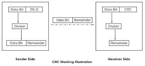
The CRC is a network method designed to detect errors in the data and information transmitted over the network. This is performed by performing a binary solution on the transmitted data at the sender’s side and verifying the same at the receiver’s side.
The term CRC is used to describe this method because Check represents the “data verification,” Redundancy refers to the “recheck method,” and Cyclic points to the “algorithmic formula.”
CRC Terms and Attributes👈
As discussed in the previous section, CRC is performed both at the sender and the receiver side. CRC applies the CRC Generator and CRC Checker at the sender and receiver sides, respectively.
The CRC is a complex algorithm derived from the CHECKSUM error detection algorithm, using the MODULO algorithm as the basis of operation. It is based on the value of polynomial coefficients in binary format for performing the calculations.
For Example:
1. x2+x+1 (polynomial equation)
2. Converting to binary format-
      -Going through the equation, we have value at the 0th position (x), value at the 1’st position (x), and the 2nd position (x2).
      -So, the binary value will be - [111]
3. Similarly for equation, [x2+1], the binary value will be, [101].
4. There is no value at the “x” position, so the value is [0].
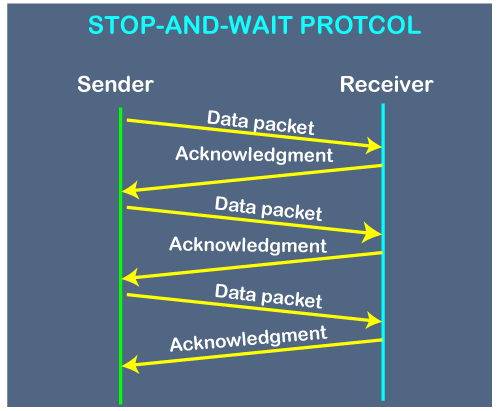
Here stop and wait means, whatever the data that sender wants to send, he sends the data to the receiver. After sending the data, he stops and waits until he receives the acknowledgment from the receiver. The stop and wait protocol is a flow control protocol where flow control is one of the services of the data link layer.
It is a data-link layer protocol which is used for transmitting the data over the noiseless channels. It provides unidirectional data transmission which means that either sending or receiving of data will take place at a time. It provides flow-control mechanism but does not provide any error control mechanism.
The idea behind the usage of this frame is that when the sender sends the frame then he waits for the acknowledgment before sending the next frame
The sliding window is a technique for sending multiple frames at a time. It controls the data packets between the two devices where reliable and gradual delivery of data frames is needed. It is also used in TCP (Transmission Control Protocol).
In this technique, each frame has sent from the sequence number. The sequence numbers are used to find the missing data in the receiver end. The purpose of the sliding window technique is to avoid duplicate data, so it uses the sequence number. Types of Sliding Window Protocol
Sliding window protocol has two types:
Go-Back-N ARQ
Selective Repeat ARQ
Go-Back-N ARQ
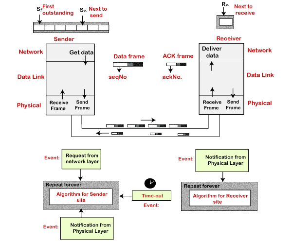
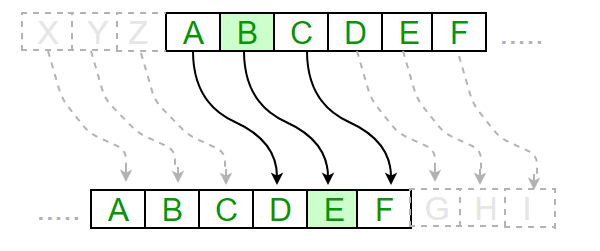
Go-Back-N ARQ protocol is also known as Go-Back-N Automatic Repeat Request. It is a data link layer protocol that uses a sliding window method. In this, if any frame is corrupted or lost, all subsequent frames have to be sent again.
The size of the sender window is N in this protocol. For example, Go-Back-8, the size of the sender window, will be 8. The receiver window size is always 1.
If the receiver receives a corrupted frame, it cancels it. The receiver does not accept a corrupted frame. When the timer expires, the sender sends the correct frame again. The design of the Go-Back-N ARQ protocol is shown below.
Selective Repaet ARQ
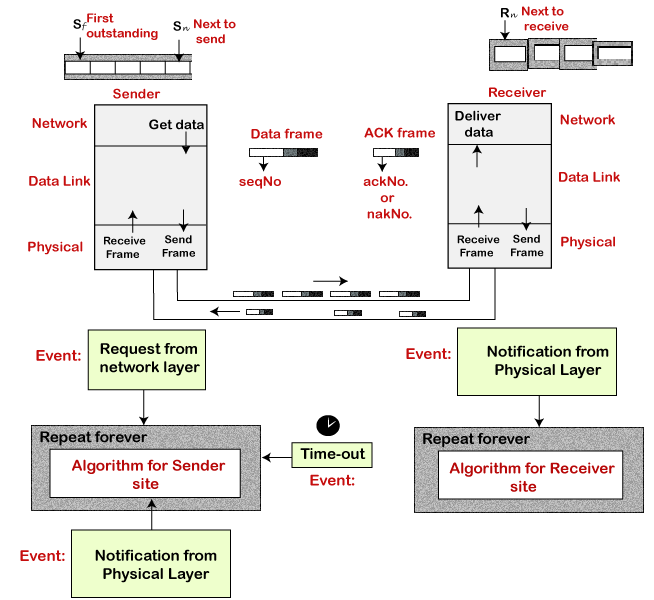
Selective Repeat ARQ is also known as the Selective Repeat Automatic Repeat Request. It is a data link layer protocol that uses a sliding window method. The Go-back-N ARQ protocol works well if it has fewer errors. But if there is a lot of error in the frame, lots of bandwidth loss in sending the frames again. So, we use the Selective Repeat ARQ protocol. In this protocol, the size of the sender window is always equal to the size of the receiver window. The size of the sliding window is always greater than 1.
If the receiver receives a corrupt frame, it does not directly discard it. It sends a negative acknowledgment to the sender. The sender sends that frame again as soon as on the receiving negative acknowledgment. There is no waiting for any time-out to send that frame. The design of the Selective Repeat ARQ protocol is shown below.
IP stands for Internet Protocol and v4 stands for Version Four (IPv4). IPv4 was the primary version brought into action for production within the ARPANET in 1983. IP version four addresses are 32-bit integers which will be expressed in decimal notation. Example- 192.0.2.126 could be an IPv4 address.
Parts of IPv4
Network part: The network part indicates the distinctive variety that’s appointed to the network. The network part conjointly identifies the category of the network that’s assigned.
Host Part: The host part uniquely identifies the machine on your network. This part of the IPv4 address is assigned to every host. For each host on the network, the network part is the same, however, the host half must vary.
Subnet number: This is the nonobligatory part of IPv4. Local networks that have massive numbers of hosts are divided into subnets and subnet numbers are appointed to that.
Different types of IP Addresses exist in the Internet Protocol hierarchy and can be utilised efficiently in a variety of settings based on the demands of hosts on a network. In general, the IPv4 Addressing System is divided into five categories of IP Addresses. All five categories are identified by the first octet of an IP address.
The five Types of classes are:
Class A
Class B
Class C
CLass D
CLass E
In distance-vector routing (DVR), each router is required to inform the topology changes to its neighboring routers periodically. Historically it is known as the old ARPNET routing algorithm or Bellman-Ford algorithm.
How the DVR Protocol Works
→ In DVR, each router maintains a routing table. It contains only one entry for each router. It contains two parts − a preferred outgoing line to use for that destination and an estimate of time (delay). Tables are updated by exchanging the information with the neighbor’s nodes.
→ Each router knows the delay in reaching its neighbors (Ex − send echo request).
→ Routers periodically exchange routing tables with each of their neighbors.
→ It compares the delay in its local table with the delay in the neighbor’s table and the cost of reaching that neighbor.
→ If the path via the neighbor has a lower cost, then the router updates its local table to forward packets to the neighbor.
Let's understand a few key points about the distance vector routing protocol :
Network Information : Every node in the network should have information about its neighboring node. Each node in the network is designed to share information with all the nodes in the network.
Routing Pattern : In DVR the data shared by the nodes are transmitted only to that node that is linked directly to one or more nodes in the network.
Data sharing The nodes share the information with the neighboring node from time to time as there is a change in network topology.
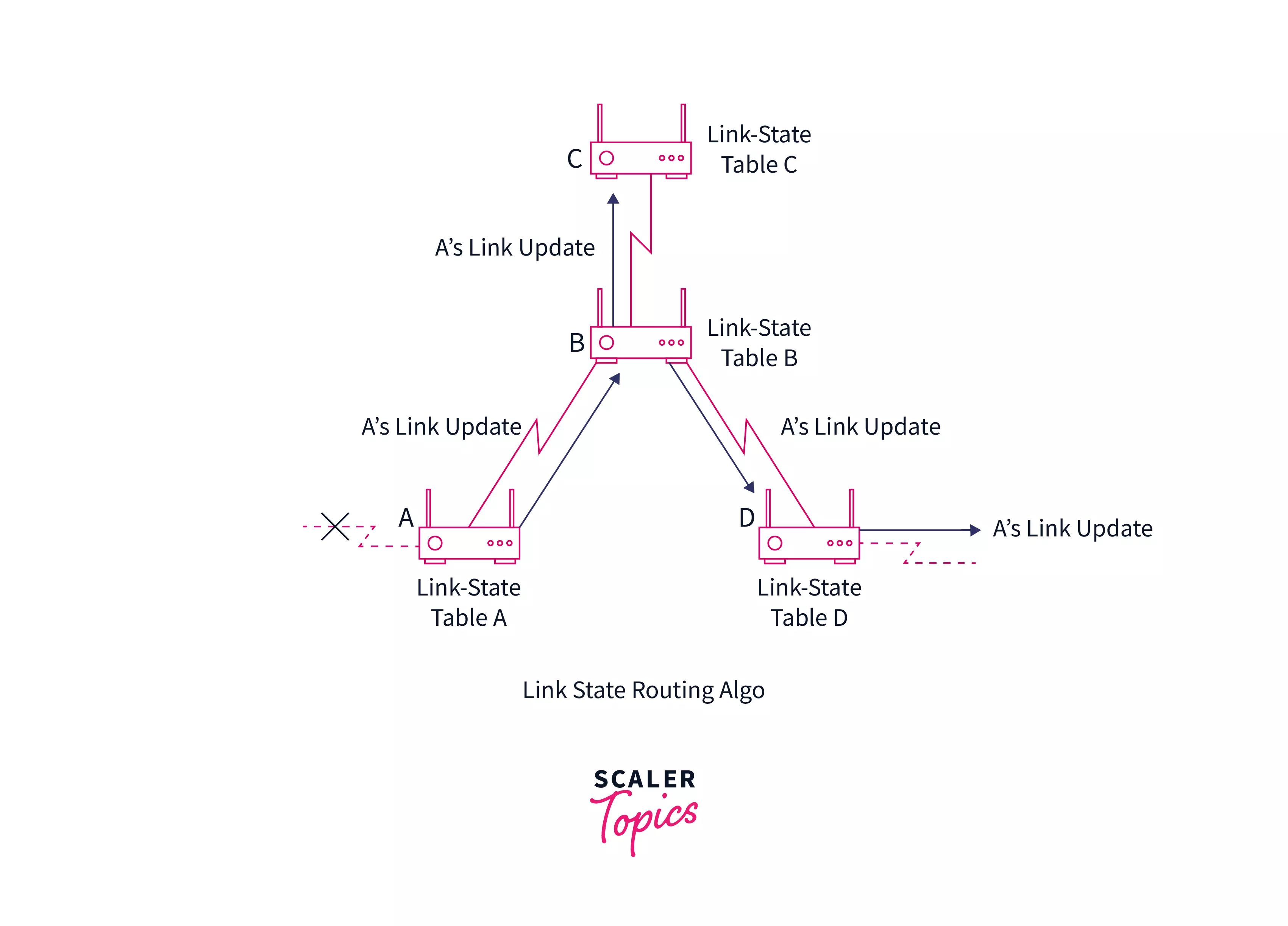
The Link State Routing Algorithm is an interior protocol used by every router to share information or knowledge about the rest of the routers on the network. The link state routing algorithm is distributed by which every router computes its routing table. With the knowledge of the network topology, a router can make its routing table. The routing table created by each router is exchanged with the rest of the routers present in the network which helps in faster and more reliable delivery of data. This information exchange only occurs when there is a change in the information. Hence, the link state routing algorithm is effective.
The Link State Routing Algorithm is an interior protocol used by every router to share information or knowledge about the rest of the routers on the network. The link state routing algorithm is distributed by which every router computes its routing table.
With the knowledge of the network topology, a router can make its routing table. Now, for developing the routing table, a router uses a shortest path computation algorithm like Dijkstra's algorithm along with the knowledge of the topology. The routing table created by each router is exchanged with the rest of the routers present in the network, which helps in faster and more reliable delivery of data.
A router does not send its entire routing table with the rest of the routers in the inter-network. It only sends the information of its neighbors. A router broadcasts this information and contains information about all of its directly connected routers and the connection cost.
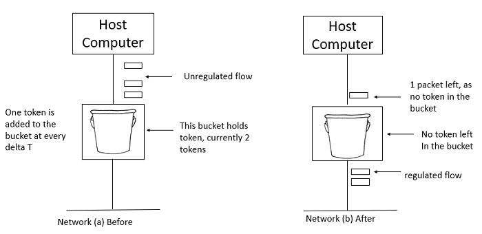
The leaky bucket and token bucket algorithms are two commonly used traffic shaping mechanisms that are used in computer networks to control the rate of traffic flow.
The leaky bucket algorithm works by maintaining a fixed-size bucket that fills up at a fixed rate, and any incoming traffic that exceeds the capacity of the bucket is discarded. The bucket leaks at a constant rate, which allows a constant rate of traffic to flow out of the bucket. This algorithm is used to control the average rate of traffic over a longer period of time.
The token bucket algorithm works by maintaining a bucket that is initially filled with a certain number of tokens. Each token represents a unit of traffic that is allowed to pass through the bucket. As traffic arrives at the bucket, a token is consumed, and if there are no tokens left in the bucket, incoming traffic is discarded. The bucket is replenished at a fixed rate with a certain number of tokens, which ensures that a certain amount of traffic can always be allowed through the bucket. This algorithm is used to control the burst rate of traffic over a shorter period of time.
Both of these algorithms are used to control the rate of traffic flow in computer networks and are used to prevent congestion and ensure fair use of network resources.
Huffman coding is a lossless data compression algorithm that uses variable-length code words to represent different symbols in a message. The code words are shorter for frequently occurring symbols and longer for less frequently occurring symbols, resulting in an overall reduction in the number of bits needed to represent the message.
The Huffman coding process has two main steps: encoding and decoding.
Encoding:
- Count the frequency of occurrence of each symbol in the message.
- Arrange the symbols in ascending order of frequency.
- Take the two symbols with the lowest frequency and create a new node with a weight equal to the sum of their frequencies.
- Replace the two symbols with the new node in the list and reorder the list.
- Repeat steps 3-4 until only one node remains.
- Assign a binary code word to each symbol, where a symbol that appears more frequently gets a shorter code word and vice versa.
- Replace each symbol in the message with its corresponding code word.
- The encoded message is the concatenation of the code words.
Decoding:
- Read in the encoded message.
- Traverse the Huffman tree, starting from the root node.
- For each bit in the encoded message, move left if it's a 0 and right if it's a 1.
- When a leaf node is reached, output the corresponding symbol and return to the root node to continue decoding the message.
- Continue decoding the message until the end of the encoded message is reached.
Huffman coding is widely used in data compression applications, such as in image, audio, and video compression.
The Caesar Cipher technique is one of the earliest and simplest methods of encryption technique. It’s simply a type of substitution cipher, i.e., each letter of a given text is replaced by a letter with a fixed number of positions down the alphabet. For example with a shift of 1, A would be replaced by B, B would become C, and so on. The method is apparently named after Julius Caesar, who apparently used it to communicate with his officials.
Thus to cipher a given text we need an integer value, known as a shift which indicates the number of positions each letter of the text has been moved down. The RSA algorithm is a public-key signature algorithm developed by Ron Rivest, Adi Shamir, and Leonard Adleman. Their paper was first published in 1977, and the algorithm uses logarithmic functions to keep the working complex enough to withstand brute force and streamlined enough to be fast post-deployment. The image below shows it verifies the digital signatures using RSA methodology. RSA can also encrypt and decrypt general information to securely exchange data along with handling digital signature verification.When using RSA for encryption and decryption of general data, it reverses the key set usage. Unlike signature verification, it uses the receiver’s public key to encrypt the data, and it uses the receiver’s private key in decrypting the data. Thus, there is no need to exchange any keys in this scenario.There are two broad components when it comes to RSA cryptography, they are:


