This project is a 'Hello World' application for the LoRaWAN Shield, developed at VIVES. This example makes use of the Simple LoRaWAN library for Mbed and the LoRaWAN Serialization library.
This example will send a single byte every 30 seconds. After each transmit, the counter is incremented by 1.
Clone the project, and install library dependencies.
git clone git@github.com:sillevl/lorawan-shield-example.git
cd lorawan-shield-example
mbed deploy
Next setup your LoRaWAN security keys in mbed_app.json.
You can now compile and run the application on your embedded board using:
mbed compile -fOpen your favorite serial terminal application and connect to the serial device.
You can change the LoRaWAN keys and the used device pin names in the mbed_app.json file. You can change or edit the values of the settings accordingly to your needs.
LoRaWAN Configuration:
"lora.device-eui": "{ 0x00, 0x00, 0x00, 0x00, 0x00, 0x00, 0x00, 0x00 }",
"lora.application-eui": "{ 0x00, 0x00, 0x00, 0x00, 0x00, 0x00, 0x00, 0x00 }",
"lora.application-key": "{ 0x00, 0x00, 0x00, 0x00, 0x00, 0x00, 0x00, 0x00, 0x00, 0x00, 0x00, 0x00, 0x00, 0x00, 0x00, 0x00 }",
Pinmappings:
"sx1276-lora-driver.spi-mosi":       "ARDUINO_UNO_D11",
"sx1276-lora-driver.spi-miso":       "ARDUINO_UNO_D12",
"sx1276-lora-driver.spi-sclk":       "ARDUINO_UNO_D13",
"sx1276-lora-driver.spi-cs":         "ARDUINO_UNO_A0",
"sx1276-lora-driver.reset":          "ARDUINO_UNO_A1",
"sx1276-lora-driver.dio0":           "ARDUINO_UNO_D2",
"sx1276-lora-driver.dio1": "ARDUINO_UNO_D3",The Node instance has 3 ways to initialize:
- Runtime LoRaWAN keys and pinmappings
- Runtime LoRaWAN keys and compiletime pinmappings
- Compiletime LoRaWAN keys and pinmappings
Provide all confugration (LoRaWAN keys and pinmappings) at runtime. This is the most flexible option.
LoRaWANKeys keys = {
    { 0x00, 0x00, 0x00, 0x00, 0x00, 0x00, 0x00, 0x00 },         // devEui
    { 0x00, 0x00, 0x00, 0x00, 0x00, 0x00, 0x00, 0x00 },         // appEui
    { 0x00, 0x00, 0x00, 0x00, 0x00, 0x00, 0x00, 0x00, 0x00, 0x00, 0x00, 0x00, 0x00, 0x00, 0x00, 0x00 } // appKey
};

Pinmapping pins = { D11, D12, D13, A0, A1, D2, D3 };  // mosi, miso, clk, nss, reset, dio0, dio1

Node node(keys, pins);

uint8_t data[] = { 0xDE, 0xAD, 0xBE, 0xEF };
node.send(data, sizeof(data));Provide LoRaWAN keys at runtime. This could be used when the keys are stored in a flash memory and are not part of the binary. This enables using multiple hardware boards with a single codebase.
Pinmappings are provided using the mbed_app.json configuration.
LoRaWANKeys keys = {
    { 0x00, 0x00, 0x00, 0x00, 0x00, 0x00, 0x00, 0x00 },         // devEui
    { 0x00, 0x00, 0x00, 0x00, 0x00, 0x00, 0x00, 0x00 },         // appEui
    { 0x00, 0x00, 0x00, 0x00, 0x00, 0x00, 0x00, 0x00, 0x00, 0x00, 0x00, 0x00, 0x00, 0x00, 0x00, 0x00 } // appKey
};

Node node(keys);

uint8_t data[] = { 0xDE, 0xAD, 0xBE, 0xEF };
node.send(data, sizeof(data));LoraWAN keys and pinmappings are provided using the mbed_app.json configuration.
Node node;

uint8_t data[] = { 0xDE, 0xAD, 0xBE, 0xEF };
node.send(data, sizeof(data));By default when creating a Node instance, the constructor will block further execution of code until the LoRaWAN connection is set up correctly.
You can override this behaviour by appending a boolean argument at the end of the constructor arguments.
Node node(false);
// continue code execution without waiting for a succesful connection
// do some other stuff here and check connection befor sending data
uint8_t data[] = { 0xDE, 0xAD, 0xBE, 0xEF };
node.send(data, sizeof(data));#include "mbed.h"
#include "Simple-LoRaWAN.h"
#include "LoRaMessage.h"
using namespace SimpleLoRaWAN;
Node node;
int main(void)
{
printf("\r\n*** Starting LoRaWAN Shield Example ***\r\n");
int counter = 0;
while(true) {
LoRaMessage message;
message.addUint8(counter++);
node.send(message.getMessage(), message.getLength());
printf("Message sent. counter: %d\r\n", counter);
ThisThread::sleep_for(30s);
}
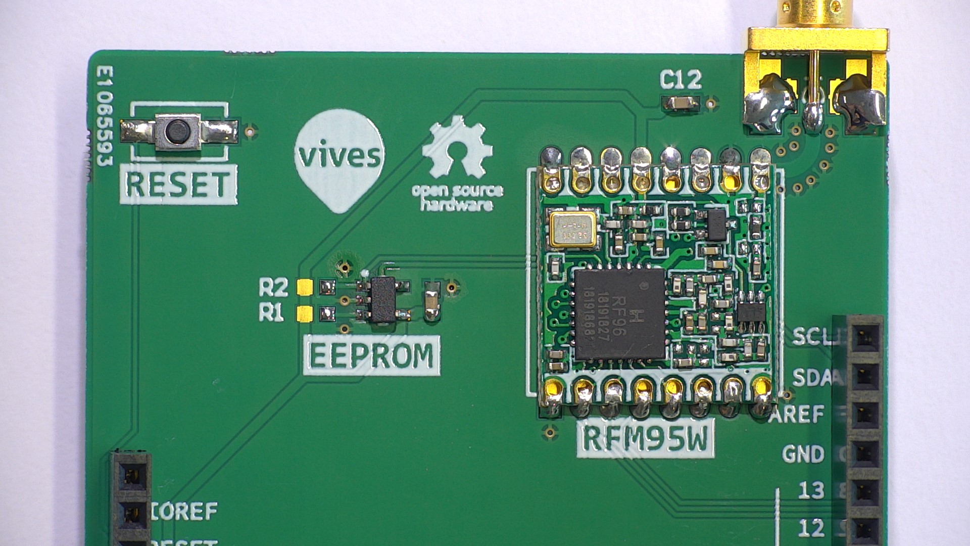
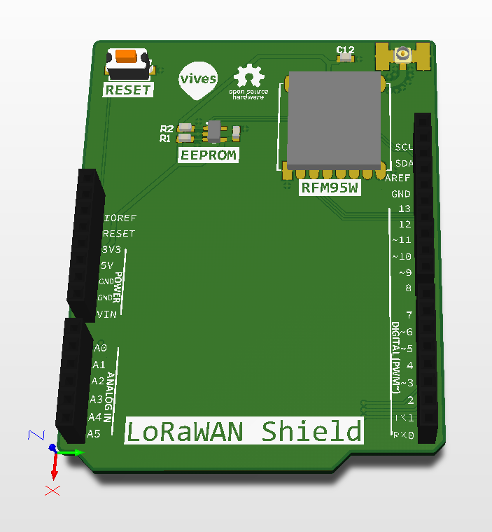
}The LoRaWAN Shield, developed at VIVES. Is an Arduino compatible board that houses an RFM95W LoRaWAN transceiver and a small EEPROM. The shield can be used on every Mbed board that has an Arduino compatible header layout.
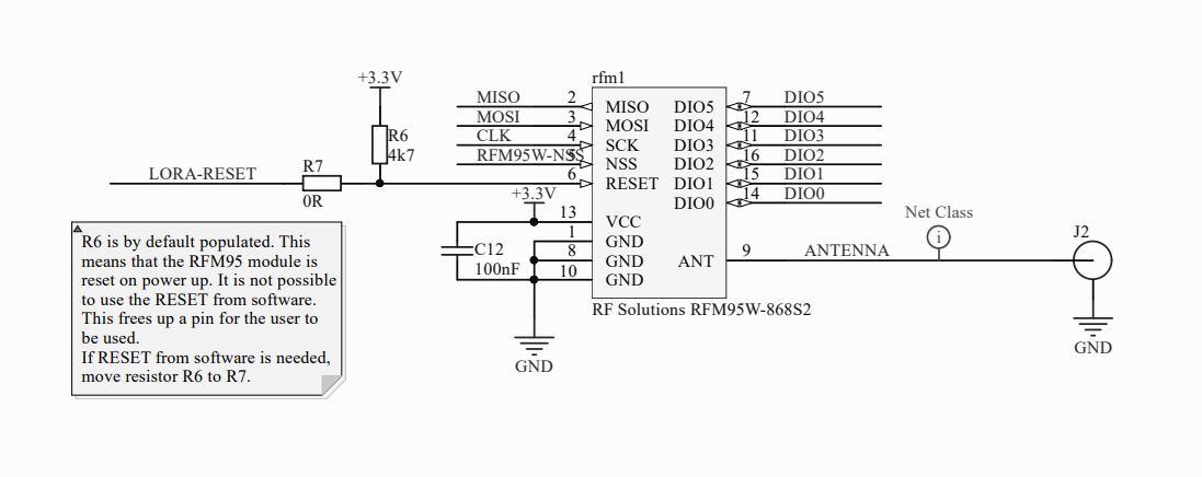
The full schematic can be found in docs/schematic.pdf
The shield uses the Arduino shield specification and can be stacked with other shields for expansion. Most pins are free to use by the user. Some pins are needed for the communication with the LoRaWAN transceiver. The board supports several pin configuration options improving compatibility with different microcontroller boards and stacked shields.
The LoRaWAN shield uses a RFM95 transceiver for LoRaWAN communication. The RFM95 uses SPI.
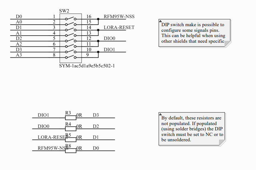
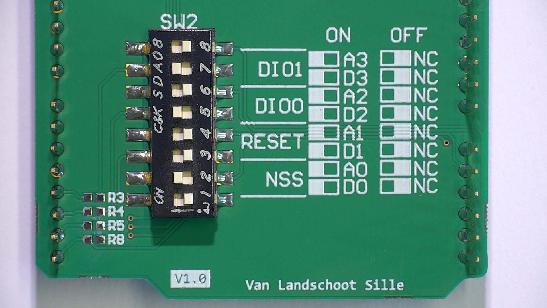
Some pins are configurable using solder bridges or DIP switches to improve compatibility with different microcontroller boards and shields.
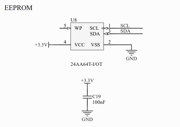
A 64kbit EEPROM is available on the shield for storing some information or settings.
The LoRaWAN Shield uses some fixed pins for SPI, together with some configurable DIP switches at the back of the shield to configure a different mapping. This feature is available to be compatible with different microcontroller boards and other sensor shields.
| Signal | Pin | configurable |
|---|---|---|
| MOSI | D11 | no |
| MISO | D12 | no |
| CLK | D13 | no |
| NSS | D0 or A0 | yes, using DIP switch / solder bridge |
| RESET | D1 or A1 | yes, using DIP switch / solder bridge |
| DIO 0 | D2 or A2 | yes, using DIP switch / solder bridge |
| DIO 1 | D3 or A3 | yes, using DIP switch / solder bridge |
This example uses the following pinmapping by default:
| Signal | Default pin |
|---|---|
| MOSI | D11 |
| MISO | D12 |
| CLK | D13 |
| NSS | A0 |
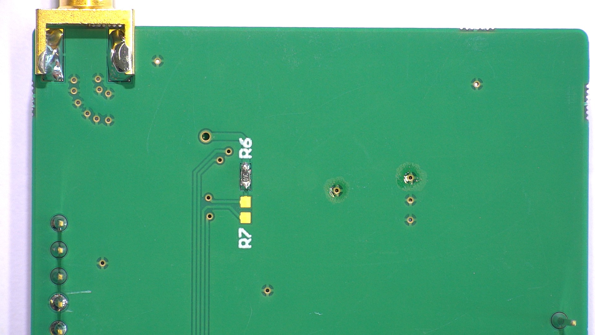
| RESET | NC (if R6 pull-up resistor) |
| DIO 0 | D2 |
| DIO 1 | D3 |
You are able to adjust this pinmapping in the mbed_app.json file. Don't forget to adjust the DIP switches accordingly.
Some microcontroller boards like ST Nucleo have hardwired serial connections for the USB UART on the pins D0 and D1. Therefore it is impossible to combine UART communications over USB and the LoRaWAN Shield using D0 and D1. Use the DIP switches to change the configuration and use A0 and A1.
By default the shield comes with a pull-up resistor R6 enabling a fixed RESET signal for the RFM95. If it is necessary that the RFM95 module needs to be able to be reset from software, R7 needs to be soldered (solder bridge or 0R resistor). This connects the RESET signal pin to the DIP switch or solder bridge R5. RESET can now be used from within software.
A reset button is provided to reset the microcontroller.
Note: This library is still in development
https://github.com/sillevl/mbed-Simple-LoRaWAN
Note: This library is still in development
https://github.com/sillevl/mbed-lorawan-serialization
The source files for the hardware can be found on Circuitmaker.
