Amiga Sparkler
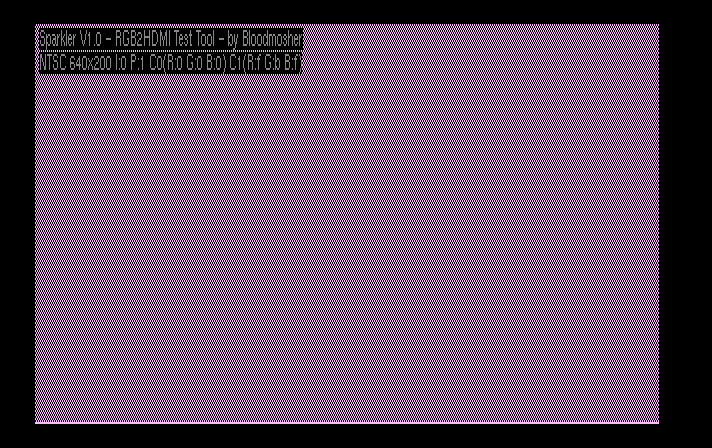
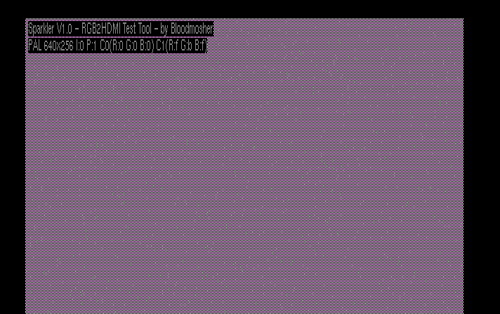
Amiga RGB2HDMI test tool used to verify boards do not have sparkling artifacts.
Instructions
- Just grab a binary from the bin folder and transfer to your Amiga and run it
- Note that this tool has only been tested on Amigas with 3.1 ROMs, and it may not work on other versions
- The default settings tend to show sparkles on boards that have issues (alternating pixels with a particular color combination on a hires non-interlaced screen).
- Refer to the on-screen help for instructions on how to vary the test pattern (press the HELP key to toggle).
- If you do see noise in the image, try the following RGB2HDMI settings changes by holding the button on your board to bring up the menu:
- Settings Menu->Overclock CPU: 40
- Settings Menu->Overclock Core: 170
- Sampling Menu->Sync Edge: Trailing with +ve PixClk
- Be sure to install a heat sink on your Pi as even the default configuration has some amount of overclocking
- In my testing, most Amiga 2000 machines do not seem to need configuration changes, but Amiga 3000 machines more commonly do. Your mileage may vary.
Video Slot V1.1 Boards
- These boards work well with no known sparkles in my testing (though some may require configuration changes as described above to eliminate noise).
- After trying numerous variations on path length, eliminating through-holes, copper fills, regulator placement, etc. the predominant issue seems to be placement of U1 relative to the other chips.
- If you can find a test pattern either from this tool or from some other source that exhibits issues, I would love to hear about it!
- Learn more about the V1.1 boards here: https://github.com/Bloodmosher/Amiga-VideoSlot-RGBtoHDMI
Video Slot V1.01 Boards
- These boards work pretty well with overclocking and the extra capacitor, but do exhibit problems on the test pattern:
Denise Adapter V2 Boards
- These boards work pretty well in most circumstances but do do exhibit problems on the test pattern.
- It would be interesting to see if the positioning of U1 could be changed (perhaps swap with the regulator?) to see if a similar outcome found on the Video Slot boards could be achieved.
CPLD Based Boards
- I have not yet tried one of these but will post results as soon as I get one built.


