 Photo courtesy of Paul D. Pape - derwellenreiter for schneidersladen, Berlin, Germany.

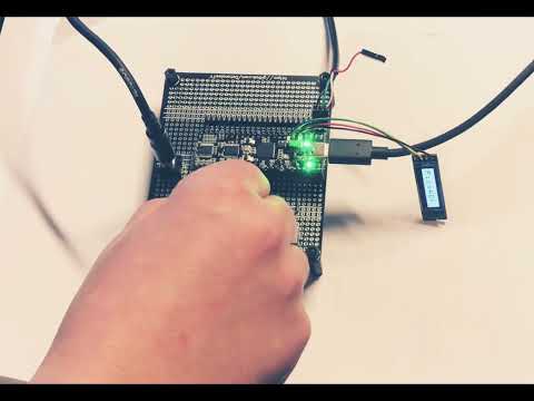
The PicoADK is a RP2040 based Audio Development Kit, which allows you to build your own digital oscillators, synthesizers, noise boxes and experiment around. It has all the base features of the Raspberry Pico, plus a high quality Audio Output, 8 Analog Inputs for connecting potentiometers, control voltage from eurorack systems or even additional input signals.
Even though it is very small, it is capable of synthesizing and outputting a very high quality sound output. Thanks to the Vult DSP language you can even create digital resonant filters, oscillators and even complete synthesizers!
You can find some sound teasers at Soundcloud.
The PicoADK can be ordered at Schneidersladen and Tindie.

- RP2040 Dual Core Cortex M0+ running at up to 400MHz
- USB Type-C connector
- 2MB Flash for Firmware and Data
- Very low noise LDO regulators (separate LDO for digital circuits and separate for analog circuits), no switching regulators
- Partially pin-compatible with RP2040 (besides a few pins internally used or rearranged), extra 4 pins on each side
- Audio DAC PCM5100A, up to 32-bit output
- Very high audio signal quality and very low noise
- Dedicated Boot and Reset Buttons
- 8 channel 12-bit ADC with up to 1MS/s, with selectable 3.3V range (on-board low-noise power supply) or range up to 5V via external VREF
- Low-Pass filter on each ADC input (fMax=48 KHz) at low-impedance (100 Ohm). With 5V VREF suitable for CV (no overvoltage protection, unipolar)
- Symbols marking special pin functions on the pin headers
- 4 LEDs on shared GPIO2-5 for debugging
- ESD Protection on USB
- SWD Debug Port
You can find the firmware template including examples at https://github.com/DatanoiseTV/PicoADK-Firmware-Template
The repository contains the I2S codec drivers, A custom build step for Vult DSP based projects and a synthesizer as an example and should be a good starting point for most projects.
Attention! The PicoADK v1.1 has the test pads for USB reversed (D/P swapped). Please make sure you take that into consideration when designing a custom board using the testpads. This is fixed in v1.1a.

Interactive pinout at https://datanoise.net/picoadk/
Some signals are routed to internal peripherals as following:
| GPIO | Function | Shared w/ Header? |
|---|---|---|
| GPIO2 | Debug LED 1 | yes |
| GPIO3 | Debug LED 2 | yes |
| GPIO4 | Debug LED 3 | yes |
| GPIO5 | Debug LED 4 | yes |
| GPIO10 | ADC128 SPI1 SCK | yes |
| GPIO11 | ADC128 SPI1 MOSI | yes |
| GPIO12 | ADC128 SPI1 MISO | yes |
| GPIO13 | ADC128 SPI1 CSn | yes |
| GPIO15 | Big Debug LED | no |
| GPIO16 | PCM5100A I2S DAT | no |
| GPIO17 | PCM5100A I2S BCLK | no |
| GPIO18 | PCM5100A I2S LRCLK | no |
| GPIO23 | PCM5100A DEMP | no |
| GPIO24 | VBUS Detect Pin | no |
| GPIO25 | PCM5102 XSMT | no |
The SPI ADC shares the GPIO10 to GPIO13, which are also present on the pin headers. Please be aware of that.
Make sure your software controls the XSMT and DEMP pins. The XSMT needs to be controled by the software to mute/unmute the audio output. With the DEMP pin you can control the Deemphasis for 44100 Hz.
By default, the ADC range is approximately 0-3.3v provided by a low-noise internal 3.3V voltage source. If you want to use 0-5V input range, you need to cut the trace on the jumper on the bottom of the PCB and bridge the VEXT position with the middle of the jumper. MAKE SURE THAT YOU CHECK FOR NON-CONTINUITY WITH A MULTIMETER between the 3.3V reference side and the middle of the jumper to make sure you've cut the bridge properly. The recommended way of cutting the trace is using a sharp blade such as an exacto knife. Use of a dremel or similar is not recommended, as it could damage the inner layers of the board
The on board LDO is only able to supply around 100mA of current on the 3.3V output. Therefore, if you are using potentiometers where the CW side is attached to GND and the CCW side is attached to 3.3V, a big current draw might destroy your boards LDO regulator.
Please consider using an external 3.3V LDO if using the ADC in 3.3V mode or modify the solder jumper on the bottom of the PCB to allow the ADC to work with up to 5V range and potentiometers to be powered by 5V. Please see the remark above at Changes required for 5V ADC range (default is 3.3v).
The most common external LDO for 3.3V operation is the AMS1117-3.3. The input of the external LDO should be attached to the VSYS pin or VBUS pin, depening on your requirements and should be decoupled with a capacitor on both input and output.
It is also recommended to connect each ADC pin with a big resistor (eg. 1M) to GND to avoid noise / floating inputs. The inputs of the ADC all have a passive low-pass filter with a cutoff frequency of 48kHz at 100 Ohms load.

- Press and Hold the B(OOT) button and press reset quickly. Afterwards release the BOOT button and you will see a RP2_BOOT drive on your computer.
The PicoADK is supported by Arduino using the Arduino Pico Package from Earle Philhower https://github.com/earlephilhower/arduino-pico
The Arduino support is currently experimental and the recommended software template is to use this repository. The PicoADK board is supported on Arduino Pico Release 2.6.4+ onwards.
In general, this board should be also supported by CircuitPython. This is also purely experimental and in an early untested stage.
More information can be found here.
- PicoADK Eurorack Module (by Datanoise)
Want your project listed? Let me know.
You can find the PicoADK at Discord right here and a community discussion board on GitHub Discussions
The STEP file for mechanical design can be found here.
 Photo courtesy of Paul D. Pape - derwellenreiter for schneidersladen, Berlin, Germany.