Low power data logger using ESP8266.
This is a portable/autonomous data logger that monitors temperature and relative humidity.
- Precision
- Power consumption
- Data storage
- Size and weight
- Pictures
- Hardware design
- Software design
- User Manual
- User Interface
- Temperature: ±0.4 °C (max), –10 to 85 °C
- Relative Humidity: ± 3% RH (max), 0–80% RH
| Parts \ Power | Running (µA) | Deep sleep (µA) |
|---|---|---|
| ESP8266 | 900 | 10 |
| SI7021 | 120 | 0.06 |
| LT1529 | 50 | 50 |
| TOTAL | 1070 | 60.06 |
Computation of power consumption for a sampling rate of 15 minutes (We estimate that the running time is approximately one seconds):
1070 * 10^-3 * 1/3600 + 60.06 * 10^-3 * 15/60 ≈ 0.015mAh
Considering a battery of 1900mAh this device could ideally store 126666 points of data. The main restriction will be the size of the flash memory.
The FS library is used to store the data in the ESP8266 internal flash memory.
If we consider the smallest flash memory available, which is 64 kilobytes, we can compute the maximum number of data points that can be stored. The file contains a header composed of the timestamp, tipically 19 chars, 19 chars for wording, the wakeup rate, tipically 3 digits and the version number, 3 digits. Each point is composed of 3 ints: milliseconds tipically 3 digits, temperature tipically 4 digits, and humidity tipically 2 digits plus 2 coma separators and a EOL char.
(64000 - (19 + 19 + 3 + 3)) / (3 + 4 + 2 + 2 + 1) = 5329 points of data
Considering a sampling rate of 15 minutes it could ideally run for more than 55 days .
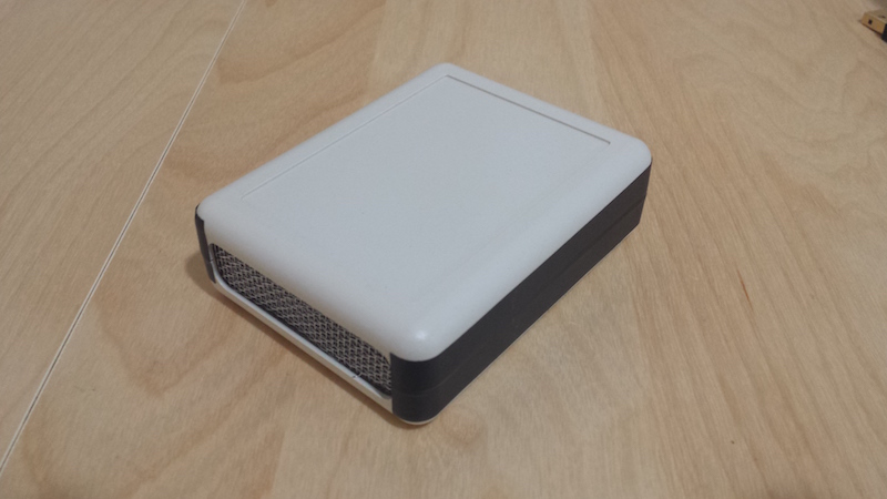
- Weight: 88g [TBR]
- Size: 90x70x28mm
Parts list:
- ESP8266 Esp07 microcontroler
- SI7021 temperature and humidity sensor
- LT1529-3.3 voltage regulator
- 22uF 100V elec. capacitor
- 1900mAh 3.7V LiPo battery
- TP4056 Li-ion charger module
- 2 switches and 2 push buttons
Remember to remove any LED that would unnecessarily draw current.
Change the constants according to your needs:
- DEFAULT_WAKEUP_RATE: This is the default value for how long should the device be sleeping between each data point. In the case the config cannot be read for some reason.
The following are deprecated, you should use the UI in AP mode instead:
- DEBUG: turn to 1 to get log messages via serial monitor.
- RETRIEVE: turn to 1 to read the list of data points, stored in the flash memory, via serial monitor.
- DELETE: turn to 1 to erase the data points from the flash memory.
To turn the AP mode on do the following:
- Make sure the circuit is energized.
- Push and maintain pushed the button connected to digital pin 4, we'll call it the Wifi button.
- Push and release the reset button.
- Wait for 3 seconds and release the Wifi button.
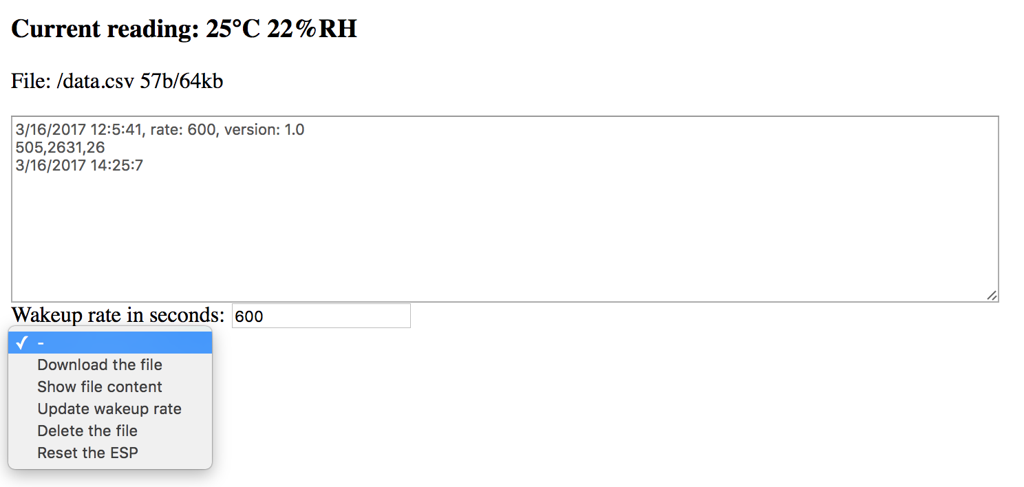
To visit the UI do the following:
- Connect your device (laptop, tablet, smartphone etc.) to the open Wifi signal named
espDataLogger. - Open a browser and go to the url http://192.168.4.1
To leave the AP mode and go back to logging mode do either one of the following:
- In the UI, select
Reset the ESP.
OR
- Push and release the reset button.
The list of actions is quite explicit about what you can do. When you download the file, the current date and time is appended so you can compute the real interval between each line of data. Also, when you update the wakeup rate, a new header line is appended to the file to keep track of the change.


