Software for the ESP2866 that sends P1 smart meter data to an mqtt broker (with OTA firmware updates)
- Peak power usage, is include as of march 2023. Implemented for and tested on the belgian smartmeters.
More details of the eMUC 1.7.1 verion can be found here: maakjemeterslim.be/
- process 15min powerpeaks
- process maximum monthly powerpeak
- process average monthly powerpeak /12 monhts
- send the 12 values as JSON over MQTT.
When upgrading this sketch from the older version that uses software serial, make sure you re-check the pins and the wiring.
The used pinout has changed since the switch to hardware serial (starting at version 0.0.2)
This setup requires:
- An esp8266 (nodeMcu and Wemos d1 mini have been tested)
- A 10k ohm resistor
- A 4 pin RJ11 or 6 pin RJ12 cable Both cables work great, but a 6 pin cable can also power the esp8266 on most DSMR5+ meters.
Compiling up using Arduino IDE:
- Ensure you have selected the right board
- Using the Tools->Manage Libraries... install
PubSubClientandWifiManager - In the file
Settings.hchangeOTA_PASSWORDto a safe secret value - Flash the software
Compiling up using PlatformIO:
- Ensure the correct board type is selected in project configuration
- In the file
Settings.hchangeOTA_PASSWORDto a safe secret value - Upload the software. Keep using the OTA Password the same during OTA updates.
Finishing off:
- You should now see a new wifi network
ESP******connect to this wifi network, a popup should appear, else manually navigate to192.168.4.1 - Configure your wifi and Mqtt settings
- To check if everything is up and running you can listen to the MQTT topic
hass/status, on startup a single message is sent.
Reset the wifi and other parameters:
- [DoubleResetDetector] (https://github.com/datacute/DoubleResetDetector) library is added.
- when pushing the reset button twice within 10 seconds (or set in the
DRD_TIMEOUT) the wifi settings will be cleared.
Connect the esp8266 to an RJ11 cable/connector following the diagram.
| P1 pin | ESP8266 Pin |
|---|---|
| 2 - RTS | 3.3v |
| 3 - GND | GND |
| 4 - | |
| 5 - RXD (data) | RX (gpio3) |
On most Landys and Gyr models a 10K resistor should be used between the ESP's 3.3v and the p1's DATA (RXD) pin. Many howto's mention RTS requires 5V (VIN) to activate the P1 port, but for me 3V3 suffices.
Expand to see wiring schema

Expand to see wiring description
When using a 6 pin cable you can use the power source provided by the meter.
Connect the esp8266 to an RJ11 cable/connector following the diagram.
| P1 pin | ESP8266 Pin |
|---|---|
| 2 - RTS | 3.3v |
| 3 - GND | GND |
| 4 - | |
| 5 - RXD (data) | RX (gpio3) |
On most Landys and Gyr models a 10K resistor should be used between the ESP's 3.3v and the p1's DATA (RXD) pin. Many howto's mention RTS requires 5V (VIN) to activate the P1 port, but for me 3V3 suffices.
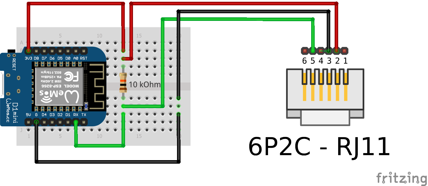
Expand to see wiring for 6 pins
| P1 pin | ESP8266 Pin |
|---|---|
| 1 - 5v out | 5v or Vin |
| 2 - RTS | 3.3v |
| 3 - GND | GND |
| 4 - | |
| 5 - RXD (data) | RX (gpio3) |
| 6 - GND | GND |

All metrics are send to their own MQTT topic. The software sends out to the following MQTT topics:
sensors/power/p1meter/consumption_low_tarif 2209397
sensors/power/p1meter/consumption_high_tarif 1964962
sensors/power/p1meter/actual_consumption 313
sensors/power/p1meter/actual_returndelivery 0
sensors/power/p1meter/l1_instant_power_usage 313
sensors/power/p1meter/l2_instant_power_usage 0
sensors/power/p1meter/l3_instant_power_usage 0
sensors/power/p1meter/l1_instant_power_current 1000
sensors/power/p1meter/l2_instant_power_current 0
sensors/power/p1meter/l3_instant_power_current 0
sensors/power/p1meter/l1_voltage 233
sensors/power/p1meter/l2_voltage 0
sensors/power/p1meter/l3_voltage 0
sensors/power/p1meter/gas_meter_m3 968922
sensors/power/p1meter/actual_tarif_group 2
sensors/power/p1meter/short_power_outages 3
sensors/power/p1meter/long_power_outages 1
sensors/power/p1meter/short_power_drops 0
sensors/power/p1meter/short_power_peaks 0
Use this example for home assistant's sensor.yaml
The automatons are yours to create. And always remember that sending alerts in case of a power outtage only make sense when you own a UPS battery :)
Although I've never had issues as a result of using this sketch reading my p1 meter, software can change, bugs can be introduced and incidents happen. Using this sketch is at your own risk ;)
Powering your meter from your p1 port should be safe as the power outlet is fully isolated from the meter but still: Don't look at me if you blowup your meter ;)
A special mention for the contributions made by other developers that make working on this sketch more fun and helped this project forward by fixing bugs and adding functionalityand to those that took the time to write down the information that helped understanding what the p1 meter was about. If you are one of them and not yet on the list, I'd love to add your name as I think it's important to mention those that enable us to have nice toys.
Standing on the heads of giants, my gratitude goes out to: