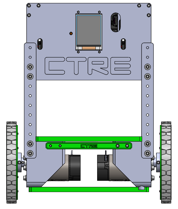
- STL files for printing the balance bot: CAD Files
- Instructions on how to assemble the balance bot: Builders Guide
- Source code to get the balance bot balancing on its own
- 3D Printer or means of printing the required STL files
- Phoenix NETMF v5.1.5.0 (Found in Phoenix 5.6.0.0 found here)
- The Balance Bot Kit sold from CTR Electronics at http://www.ctr-electronics.com/
This is a demo robot that shows how PID can be used to control something inherently unstable (an inverted pendulum) in a very controllable manner.
This is done through various control schemes, that you can look at here
- Assemble the hardware as shown in the Builders Guide.
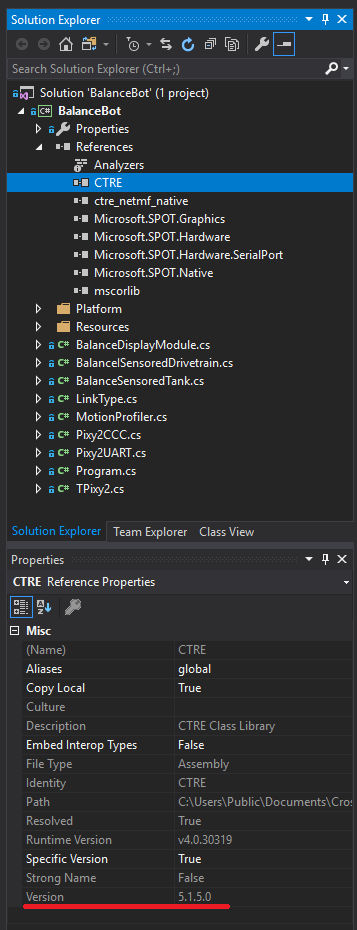
- Ensure Phoenix 5.6.0.0 is installed and Phoenix NETMF 5.1.5.0 is referenced in the solution explorer.
http://www.ctr-electronics.com/installer-archive
This can be confirmed below...
- Flash all hardware using Phoenix Lifeboat.
- HERO firmware is 1.2.0.0
- Talon firmware is 11.8
- Pigeon firmware is 0.41
- Deploy code to HERO.
- Done!
All the controls are configurable within the source code, you can change any button you want. Default controls are:
- A - Re-Zero the balance bot to make its current pitch the 0 pitch
- X - Enable closed-loop control of the balance bot to attempt to balance on the surface
- Start - Enable Pixy Control mode
- Shift from D input to X input mode - Disable robot
- Shift from X input to D input mode - Enable robot
Gain Tuning Controls:
- RB - Increment currently selected gain by increment amount shown in yellow above gains
- LB - Decrement currently selected gain by increment amount shown in yellow above gains
- Back - Cycle increment amount between 0.001 -> 0.010 -> 0.100 -> 1.000 -> 10.00 -> 0.001
- B - Cycle currently selected gains by P -> I -> D -> P
- Y - Cycle currently selected gains by Top -> Mid -> Bottom -> Top
There are also various features available that allow for better control
- Cascaded PID Loop
- (Pixy Camera PID) feeds desired velocity to maintain distance into a
- Velocity Control PID feeds angle to maintain velocity into a
- Balance Control PID outputs percent output to maintain angle
- The outer control loop (Velocity) runs at a slower rate than the inner loop (Balance) to ensure the balance loop has time to react to any velocity changes. This is key to ensuring the robot balances properly.
- Fall Detection
- When the robot surpasses a specified angle for too long, it will have tipped over.
- When tipped over, the robot must be uprighted for some time before it will be given control again and attempt to balance again.
- The tipped over angle changes based on the velocity of the robot, if it's moving forward a great velocity, it is unable to accelerate in that direction for very much, so the fall detection recognizes it is unable to recover if angled in the direction of travel and determines it has tipped over
- Likewise, if the robot is moving forward at a great velocity, it is able to angle against the direction of travel at a greater angle than normal due to it having more room to accelerate without having it tipped over.
- Pixy Camera
- Every robot has the ability to enable Pixy Control mode by pressing start on the gamepad.
- Pixy Control is visible due to the screen having turned blue on the robot
- If the robot has a Pixy Camera attached to it, it will actively look for blue objects with a similar luninence to the Display Module Screen
- If it finds an object that matches what it's looking for, it will take control away from the user and attempt to face in its direction and maintain a distance such that the height of the target matches a predefined height in the code.
- If there is no Pixy Camera attached to a robot with Pixy Control active, it will just have the blue screen on and have full user control, other robots will still be able to follow it.
- Low Battery Voltage Detection
- Once the battery is measuerd to be less than what the robot expects a battery voltage to be at (currently set to 11.00V), the robot will enter Low Battery mode.
- While in Low Battery mode, the robot will feel sluggish and the display will show a red background if not in Pixy Control mode.
- Once the robot is in Low Battery mode, it will not exit until the voltage reaches a good voltage (currently 11.50V). This is to ensure the robot does switch between Low Battery and good battery due to motor loads.
- This feature is to ensure the battery does not discharge below a certain point, and to let the user know the battery is low so they can charge it.
The screen is used for debugging purposes, when dialing in gains it's useful to be able to change the gains on the fly to test various gains without having to re deploy the application.
It also displays the current pitch the robot is at, along with the battery voltage it is measuring, whether closed looping is enabled or not, and what the percent output to the motors are at. All of this is useful for debugging various issues with the robot.
Lastly, there are points on the screen, normally 'o's. They show what direction each wheel of the robot is traveling in. This is useful as it allows the builder to double check they did the wiring correctly. If the robot is pushed forward such that the wheels turn, both of the displays should show up as a '+'. If just one wheel is pushed forward, only that side should show up as a '+'. Likewise for going backwards, they should show up as a '|' or when viewed directly at it a '-'.
Besides this, it will turn blue when the robot is in Pixy Control mode, this allows other pixy cameras to detetct where the robot is and attempt to face towards the blue-screened robot and maintain a distance away from the robot.

