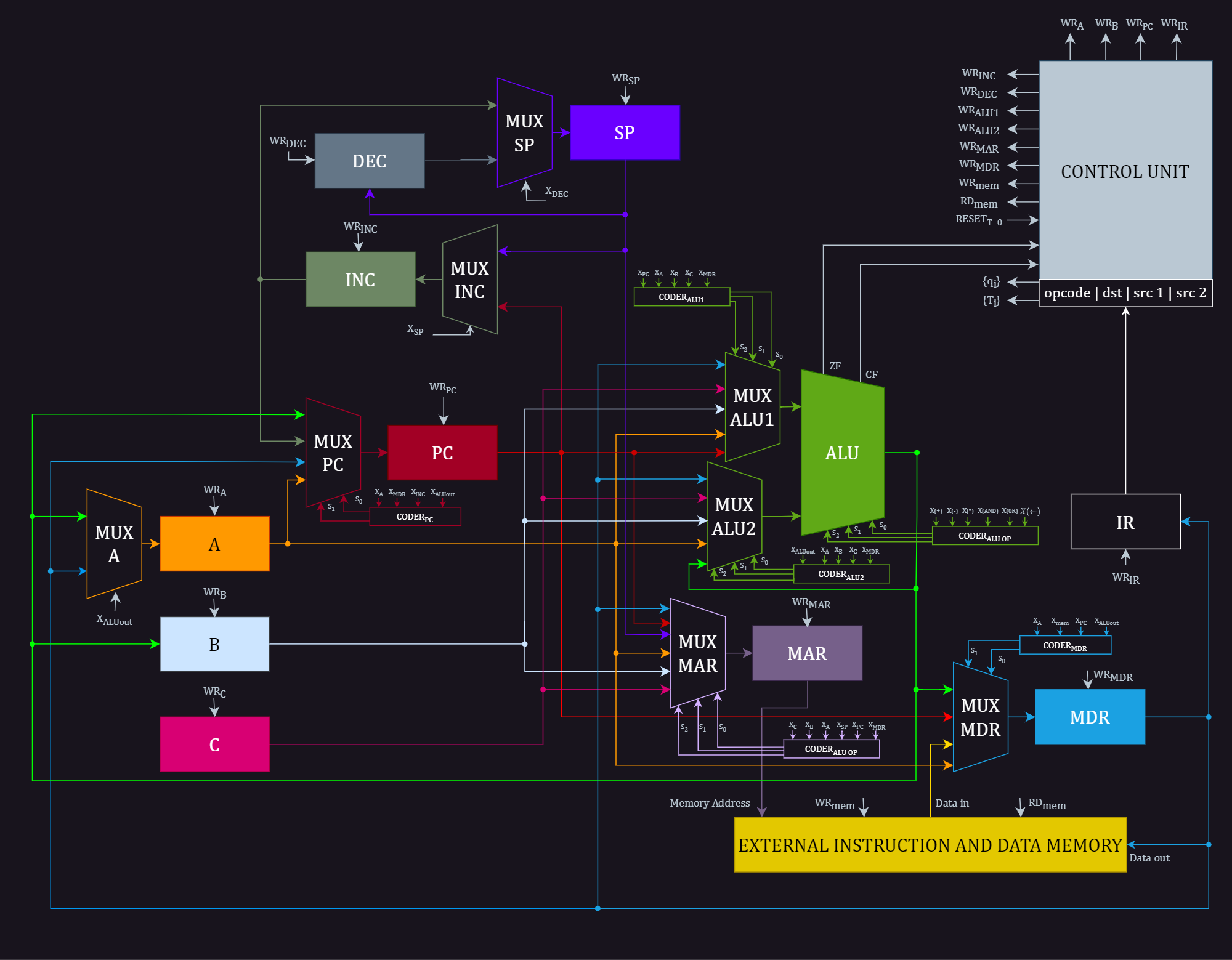
Link to Full Resolution Datapath Diagram
- Registers (A, B, C): These are storage units for temporary data within the CPU.
- Arithmetic Logic Unit (ALU): The ALU performs mathematical operations (like addition, subtraction) and logical operations (like comparisons) on data.
- Program Counter (PC): This register stores the memory address of the next instruction to be executed.
- Memory Address Register (MAR): This holds the memory address from which data will be read or written.
- Memory Data Register (MDR): This register acts as a buffer, holding the data that has been read from or will be written to memory.
- Instruction Register (IR): This register holds the currently fetched instruction.
- Control Unit: This is the "brain" of the datapath, generating control signals that dictate the operation of all the other components.
-
Instruction Fetch:
- The PC holds the address of the next instruction.
- This address is sent to the memory via the MAR.
- The instruction is fetched from memory and stored in the MDR.
- The MDR contents are then transferred to the IR for decoding.
-
Instruction Decode:
- The control unit interprets the instruction in the IR.
- It determines the operation to be performed, the source of operands, and the destination for the result.
-
Operand Fetch:
- If the operation requires data from registers, the registers A, B, or C are selected based on the instruction.
- If data needs to be fetched from memory, the address is calculated and sent to the MAR.
- The data is fetched from memory and stored in the MDR.
-
Execute:
- The ALU performs the operation specified by the instruction on the fetched operands.
- The result is stored in a register or written back to memory, depending on the instruction.
-
Write Back (if applicable):
- If the instruction's result is to be stored in a register, it's written back to the appropriate register (A, B, or C).
- If the result is to be stored in memory, the address is sent to the MAR and the data is written to the MDR.
- Multiplexers (MUX): These components select one of several inputs to pass through as output. They are used to control the flow of data in the datapath based on control signals.
- Decoders: These components transform the instruction into signals that control the operation of other components in the datapath.
- Incrementers (INC): These units are used to increment the PC, ensuring that the CPU fetches the next instruction in sequence.
- This datapath has a limited instruction set due to the small number of registers and the relatively simple ALU.
- It is designed for educational and illustrative purposes rather than representing a real-world, high-performance CPU.
