Alternative Firmaware for Chinese "14 Bit" Sim Racing Handbrake by Daniel Korgel
The 12 and 14 Bit Version of the chineses SimRacing Handbrake use an Arduino Pro Micro and a hall sensor.
This sketch is desigend as a replacement firmware to allow modifcations like connecting more buttons to the arduino and so using more of it's potential.
The sktech in this repository is a direct replacement and works just like the original software but also includes an example for 2 additional buttons.
- Repository: https://github.com/MHeironimus/ArduinoJoystickLibrary
- Direct Download: https://github.com/MHeironimus/ArduinoJoystickLibrary/archive/master.zip
If your IDE is using default directories, you can execute the deploy.bat to Install the library, otherwise you need to copy the Joystick directory into your Arduino/libraries directory manually.
Download / Clone this repository or just the sktech and open the "ChineseHandbrakeCustomFirmware.ino" with your Arduino IDE:
- Sketch Only: https://raw.githubusercontent.com/Dakor91/Chinese-SimRacing-14Bit-Handbrake-Custom-Firmware-Arduino-Sketch/master/ChineseHandbrakeCustomFirmware.ino
- Repository: https://github.com/Dakor91/Chinese-SimRacing-14Bit-Handbrake-Custom-Firmware-Arduino-Sketch/archive/master.zip
Then...
- Conntect your Handbrake and select the corresponding COM port of the device, which will be titled "Arduino Leonardo".
- Select "Arduino Leonardo" as the Board Type.
- Compile and Deploy the Sketch.
Done!
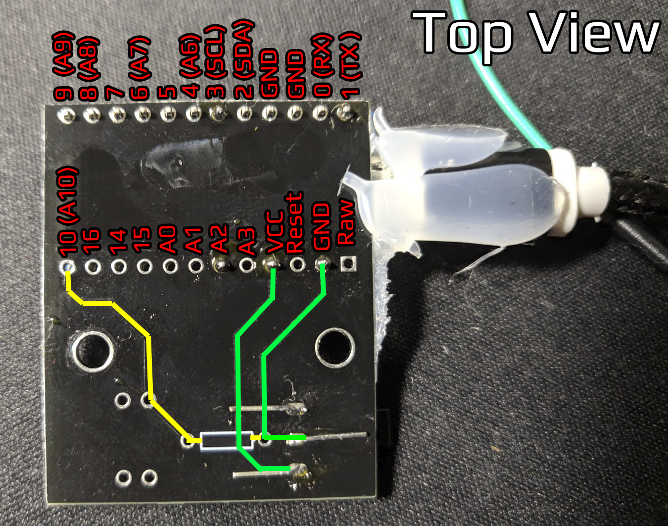
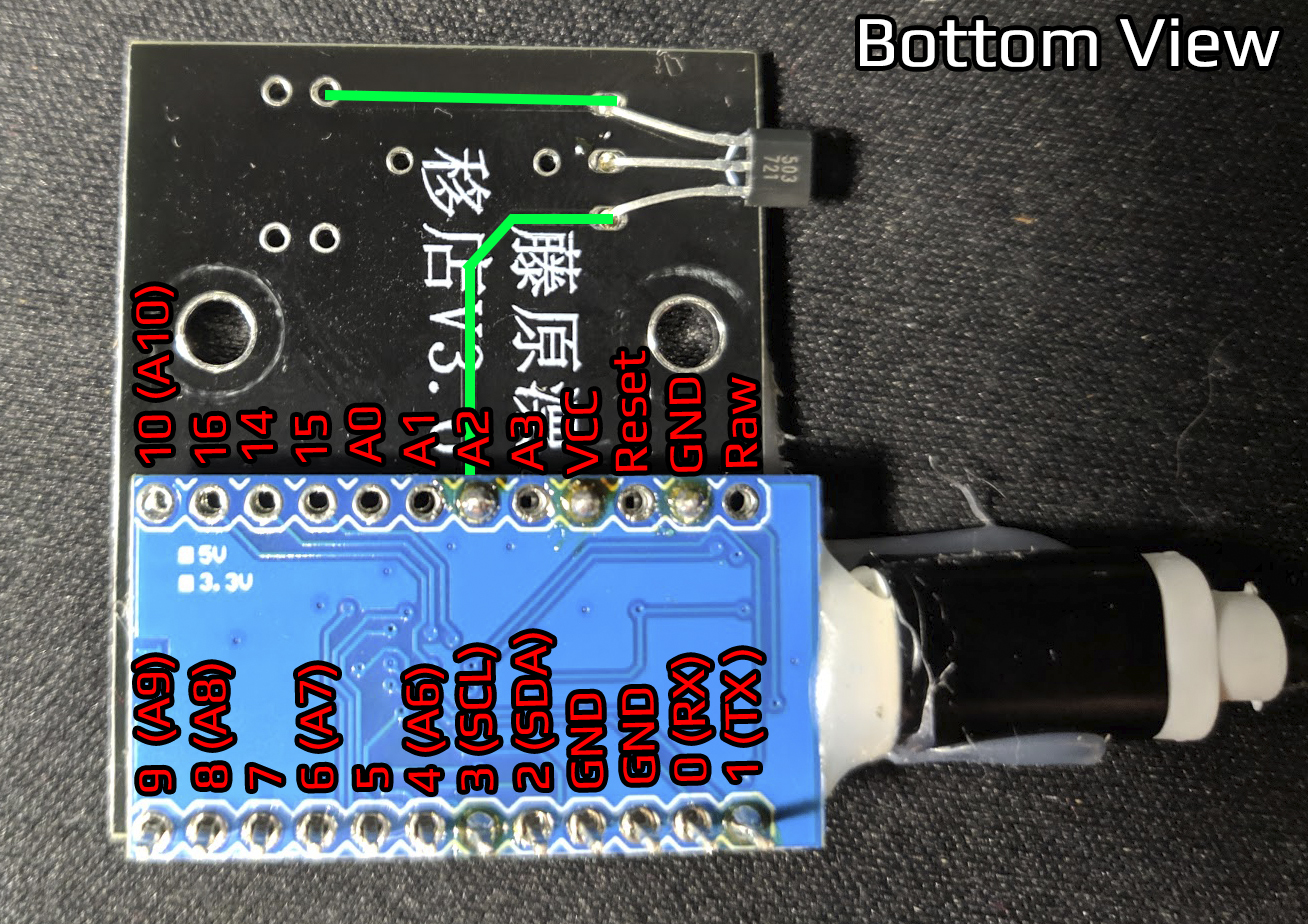
Within the handbrake there's a simple PCB with an Arduino Pro Micro and a Hall Sensor.
On the pcb titled version 3.0 the hall sensor is conntector to GND, VCC and A2. The PCB has another lead to pin 10, but it's not connected to anything else, due to a missing resistor.
Pin 3 and pin 1 of the arduino were also soldered on my board, but there are no leads going anywhere. To be sure I measured both and found that they are not connected to anything that's measurable on the pcb. I assume they are just soldered for stabilization.
Note: I know that there's at least a version 4.0 of this PCB, but I don't know the exact differences.


