This Python Desktop GUI controls 8 Arduino GPIO pins, which can be hooked up to any multiplexer. Different Mux inputs can be cycled through at a regular rate, or a singular input can be selected. The analog input pin on the Arduino displays 0-5V in real-time, and all those data points can be saved in a .csv file format.
Plug the Arduino into the computer and figure out its COM port (on Windows machines, it'll be something like COM#: on Linux machines, /dev/ttyS#).
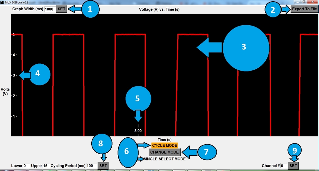
Run the mux_display.py program with Python 3.X. Follow the prompts and connect to the Arduino's COM device. You should see the following program:
- 1
- "Graph Width" means how 'wide' the graph is with respect to time. It's default value, 1000 milliseconds (1 second) means that 1 second of information is being presented on the screen. To change it, change the number in the textbox and press SET to see your change enacted.
- If you want to "zoom in" so you can see more details on a curve, change the value to a smaller number. If you feel the graph is moving too quickly, change the value to a higher value.
- 2
- The Export To File button will save all information since the start of the session into a .csv file to be opened up in Microsoft Excel or other software. Press this button, and wait until a popup message tells you if the file was written succesfully or not. If no popup message appears, check the console window for any errors raised. All files are saved in src/dist/exported_files or in the directory where the program is running.
- 3
- The red lines on the black background is the continually updated output information. It is voltage as a function of time.
- 4
- These are the voltage axis labels. As you can see, all outputs are between 0-5V volts. There is about 5mV of resolution available.
- 5
- These are the moving time axis labels, in seconds. The voltage is sampled somewhere between 500->1000Hz, meaning around 1ms of time resolution.
- 6
- This device is capable of operating in two modes: CYCLE MODE or SINGLE SELECT MODE. The highlighted selection is what mode you are currently in.
- CYCLE MODE lets you choose a range of MUX inputs to cycle through at a set rate.
- SINGLE SELECT MODE lets you choose 1 channel at a time and stay there.
- This device is capable of operating in two modes: CYCLE MODE or SINGLE SELECT MODE. The highlighted selection is what mode you are currently in.
- 7
- Pressing this button will switch you between CYCLE MODE and SINGLE SELECT MODE. You will only be able to see the controls for what mode you are currently in, the other controls will be hidden.
- Note that this button just switches between the modes, you must still press SET for your respective mode to enact the changes.
- 8
- Configuration options for CYCLE MODE. Change any numbers in the textboxes, then press SET to start cycling mode with those parameters.
- PARAMETERS
- Lower -> The 0-based lower bound of MUX inputs to cycle through
- Upper -> The 0-based upper bound of MUX inputs to cycle through
- For example, if Lower is 0 and Upper is 15, the program will cycle through range b0000 -> b1111.
- If Lower is 7 and Upper is 12, the program will cycle through range b0111->b1100
- PARAMETERS
- Cycle Period (ms) -> The amount of time, in ms, to "stay" at each MUX input before cycling to the next.
- For example, if Cycle Period is 100ms, the program will change inputs 10 times a second.
- Configuration options for CYCLE MODE. Change any numbers in the textboxes, then press SET to start cycling mode with those parameters.
- 9
- Configuration options for SINGLE SELECT MODE. Change any numbers in the textbox, then press SET to change to start single select mode with those parameters.
- PARAMETERS
- Channel # -> The channel number you wish to look exclusively at.
- For example, if Channel# is 3, the program will output b0011 to the multiplexer, staying on that channel until something else changes it.
- PARAMETERS
- Configuration options for SINGLE SELECT MODE. Change any numbers in the textbox, then press SET to change to start single select mode with those parameters.
You can directly connect to the device via serial and interface with it that way. Open puTTY or any other serial program, find the COM port of the device, and choose 115200 for the BAUD.
When connected, you will probably see a large stream of data characters. Send a 'd' to toggle that off. You can then press 'h' to display the help prompt.
The microcontroller program was written in C/C++ using the Arduino IDE software. It is flashed to a 328P SoC with the Arduino Bootloader on it. To modify the source code, simply download Arduino IDE, make any changes, and press the "Upload" button to see them enacted on the computer.
The desktop software is written in Python3.4, using tkinter as the GUI controller and pySerial as the serial controller. To modify the source, download any version of Python 3.X. Make any modifications in your IDE of choice, then run "python mux_controller.py" to run it.
It is made into a standalone executable for Windows using py2serial (in other words, target computers don't need to have python installed for the program to work). To do that, download the Python 3.X version of py2serial. Go to the src directory, and the run this command: "py -3.4 create_standalone_executable.py py2exe". The standalone executable will be located in src/dist/mutex_display.exe. Note that you most likely need python3.4 to create the standalone executable.
- arduino_code
- The C/C++ code file in the Arduino .ino format. Open this with Arduino IDE to flash the arduino with this software.
- dist
- When creating a standalone Windows executable, where the final distributed software goes
- manual
- The manual of all software components (similar to this README)
- serial
- The external PySerial package referenced by the mux_display.py
- create_standalone_executable.py
- The python script used to create a standalone Windows Executable
- icon.ico
- The icon used by the mux_display.py program
- mux_display.py
- The main Python GUI program that interacts with the Arduino to control a multiplexor
- README.md
- This file