SmartThings Connected Wired Security System using a NodeMCU ESP8266
This project will help you connect SmartThings to wired contact sensors (for doors and windows) and motion sensors that you may already have pre-wired in your home from a built-in home security system. There are three components to the project:
- a SmartThings Device Handler for contact sensors and motion sensors
- a SmartThings SmartApp that receives HTTP POST messages
- Lua code for the NodeMCU device that connects your wired system to the cloud
Background
The house I live in was built in the early 90s and came with a built-in home security system. I'm not interested in using the outdated alarm system panel, but I wanted to connect the contact sensors in my doors and the motion sensor in my house to SmartThings. I learned about the NodeMCU ESP8266, a small, cheap, programmable development board that has WiFi built in. I set out to connect my door and motion sensors to the NodeMCU and program it to update SmartThings every time a change is detected.
Materials
- A NodeMCU development board. This is the one I bought on Amazon for about $8 with Prime shipping.
- A basic breadboard or 3-pack.
- Some extra wires of various male/female combinations.
- A microUSB power supply or try one of these other ways to power the device
- To connect your alarm siren or strobe light, you'll need a relay that the board can switch with a 3.3V signal. These work well and are only a few dollars each (ship from China).
Update: Later on I saw this NodeMCU board with a base that looks like it eliminates the need for a breadboard. And this kit also includes 40 jumper cables making it an attractive all-in-one starter set.
Update 2: One user reported that he had success with this board which has 7 GPIO pins available for connecting sensors. With the board I bought and linked above, I could only get 4 or 5 pins working reliably. This may be a good option if you have more sensors and don't want to set up multiple devices.
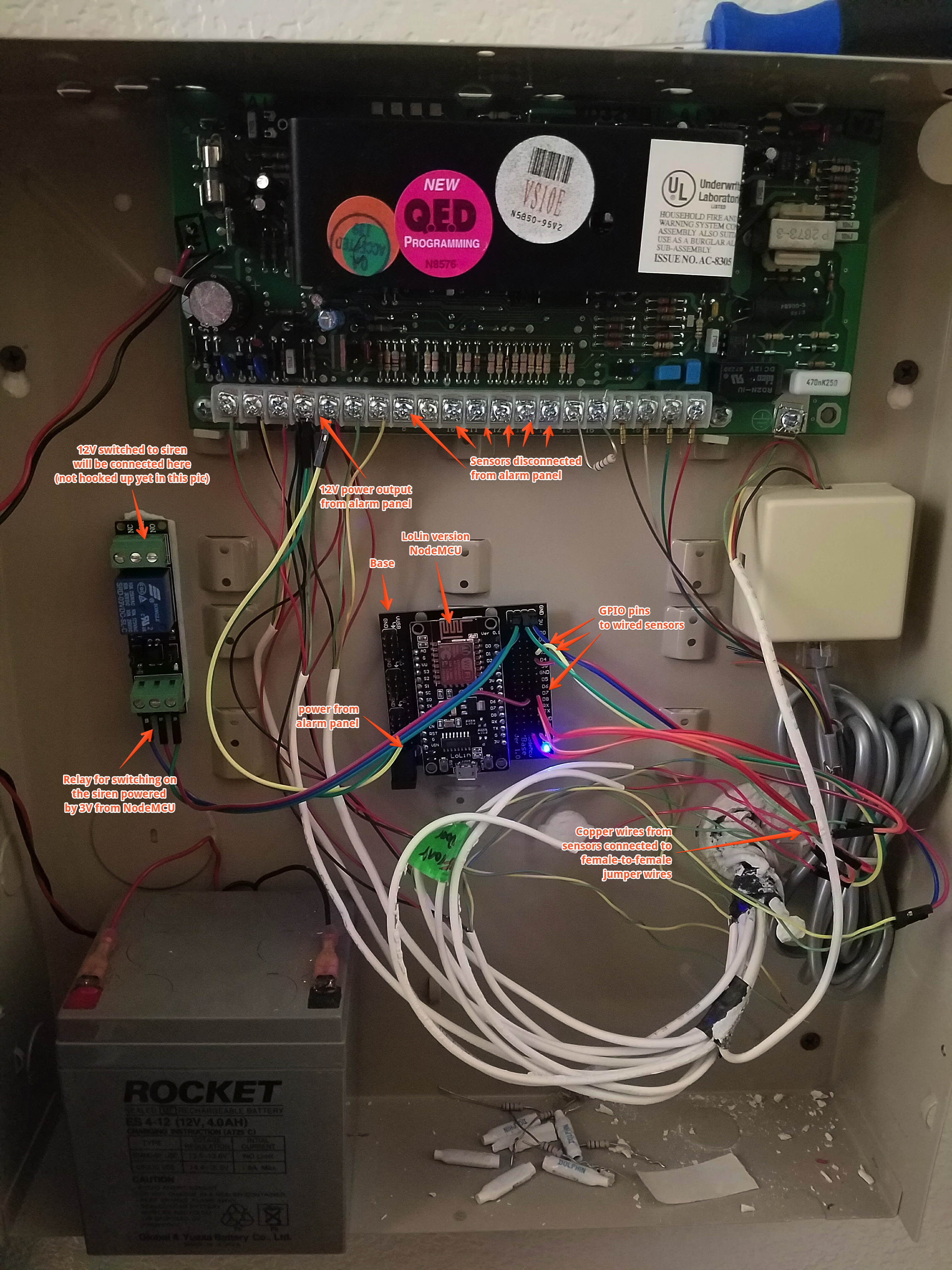
Annotated Photo
Updates
v1.5 / 2017-04-07
Feature: Connect a wired siren and/or strobe. Integrates seamlessly with the Smart Home Monitor app.
IMPORTANT: Read the upgrade notes if you're upgrading from an earlier version.
v1.3 / 2017-03-29
Feature: Blink the onboard LED on successful communication with SmartThings. To enable set blink_led = true in
variables.lua
Feature: Reliable polling. Configure by setting poll_interval in variables.lua to a number to indicate the number
of seconds between polling for sensors that may have gotten out of sync.
v1.2 / 2017-03-06
Feature: Reports the status of each sensor upon startup.
v1.1 / 2017-02-18
Feature: Support for wired smoke detectors.
v1.0 / 2017-02-09
Initial release.
Step by Step Setup Guide
1. Getting Started
- Clone or download this repository and open up the
luafolder. - Copy or rename
variables.lua.exampletovariables.lua - Copy or rename
credentials.lua.exampletocredentials.lua - Open up
credentials.luain your favorite text editor and put in your WiFi SSID and password - Also open up
variables.lua. We'll be completing this as we set up things in SmartThings.
2. Create Device Handler(s) in SmartThings
- Log in to the SmartThings IDE -> My Locations -> click on your location
- Go to My Device Handlers -> Create New Device Handler
- Click the From Code tab and paste the content of one of the device handlers and save:
- NodeMCU Connected Contact Sensor
- NodeMCU Connected Motion Sensor
- NodeMCU Connected Smoke Detector
- NodeMCU Connected Alarm
- Click Publish -> For Me
- Repeat for the other device handler if you need both types
3. Create Devices in SmartThings
You'll need to create a device for each sensor that you plan on connecting. Repeat these steps for each sensor:
- In the SmartThings IDE, go to My Devices
- Click New Device and fill out the form giving your device a name like "Front Door"
- In the Device Type dropdown, select either the NodeMCU Connected Contact Sensor or NodeMCU Connected Motion Sensor that you created earlier.
- The Device Network Id doesn't seem to really matter, I just put a number.
- Once you've created the device, make note of the device's URL. It will be something like
https://graph-na02-useast1.api.smartthings.com/device/show/22433333-1111-41dc-0000-00000000000. The last part of the url is the DeviceId. Copy this DeviceId to thevariables.luafile.
If you're connecting your alarm system siren or strobe, follow these steps:
- Click New Device and fill out the form giving your siren a name like "Alarm"
- In the Device Type dropdown, select NodeMCU Connected Alarm
- Put any unique string in for Device Network Id. This will be overwritten later when you connect.
4. Create the SmartApp
The SmartApp receives data from your NodeMCU device, and updates the status of your devices in SmartThings.
- Go to My SmartApps -> New SmartApp
- Click the From Code tab and paste the content of the SmartApp:
- Once the SmartApp is created, click the edit icon or go to App Settings -> OAuth and enable OAuth and save.
- Make note of the OAuth Client ID and Client Secret, you'll need these later.
- Click Publish -> For Me
5. Generate an OAuth token
The OAuth token is used to sign HTTP requests from the NodeMCU to the SmartApp you just created. SmartThings has documentation of this process here.. We'll be going through the OAuth flow manually to capture the token which can then be saved on the NodeMCU.
-
Copy and paste the below web address into your browser and replace
YOUR-SMARTAPP-CLIENT-IDwith the OAuth Client ID from the SmartApp created eariler.https://graph.api.smartthings.com/oauth/authorize?response_type=code&client_id=YOUR-SMARTAPP-CLIENT-ID&scope=app&redirect_uri=http://localhost:3000/auth -
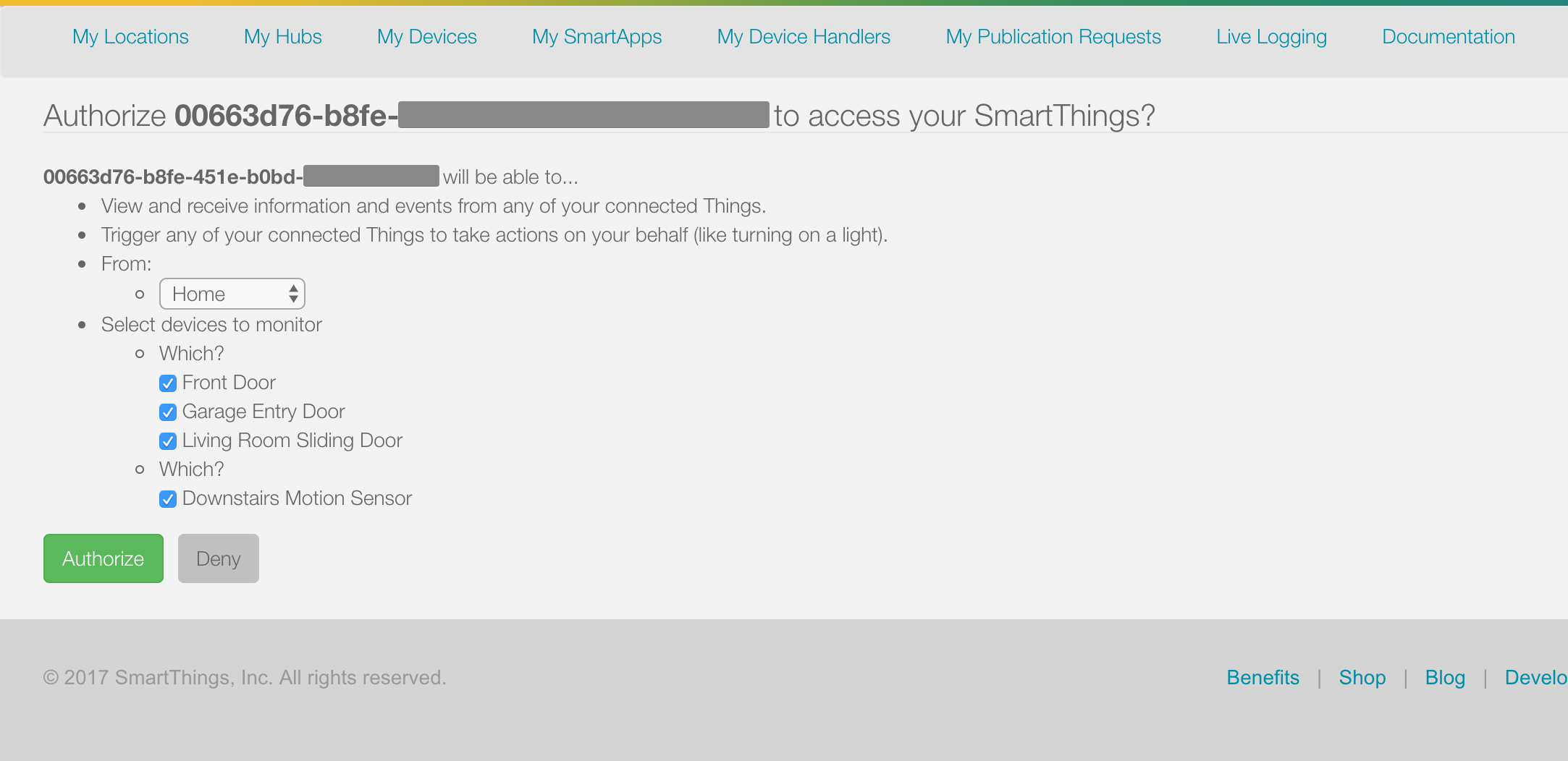
You'll see a page like this allowing you to authorize the devices you set up earlier:
-
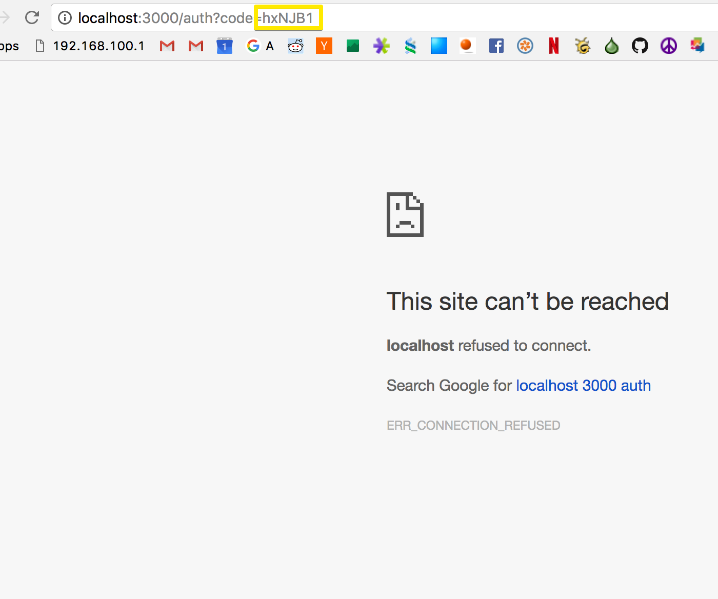
Once you click Authorize, you'll be redirect to http://localhost:3000/auth which will error. That's ok! It wasn't supposed to work. All you need is the code out of the URL parameter:
-
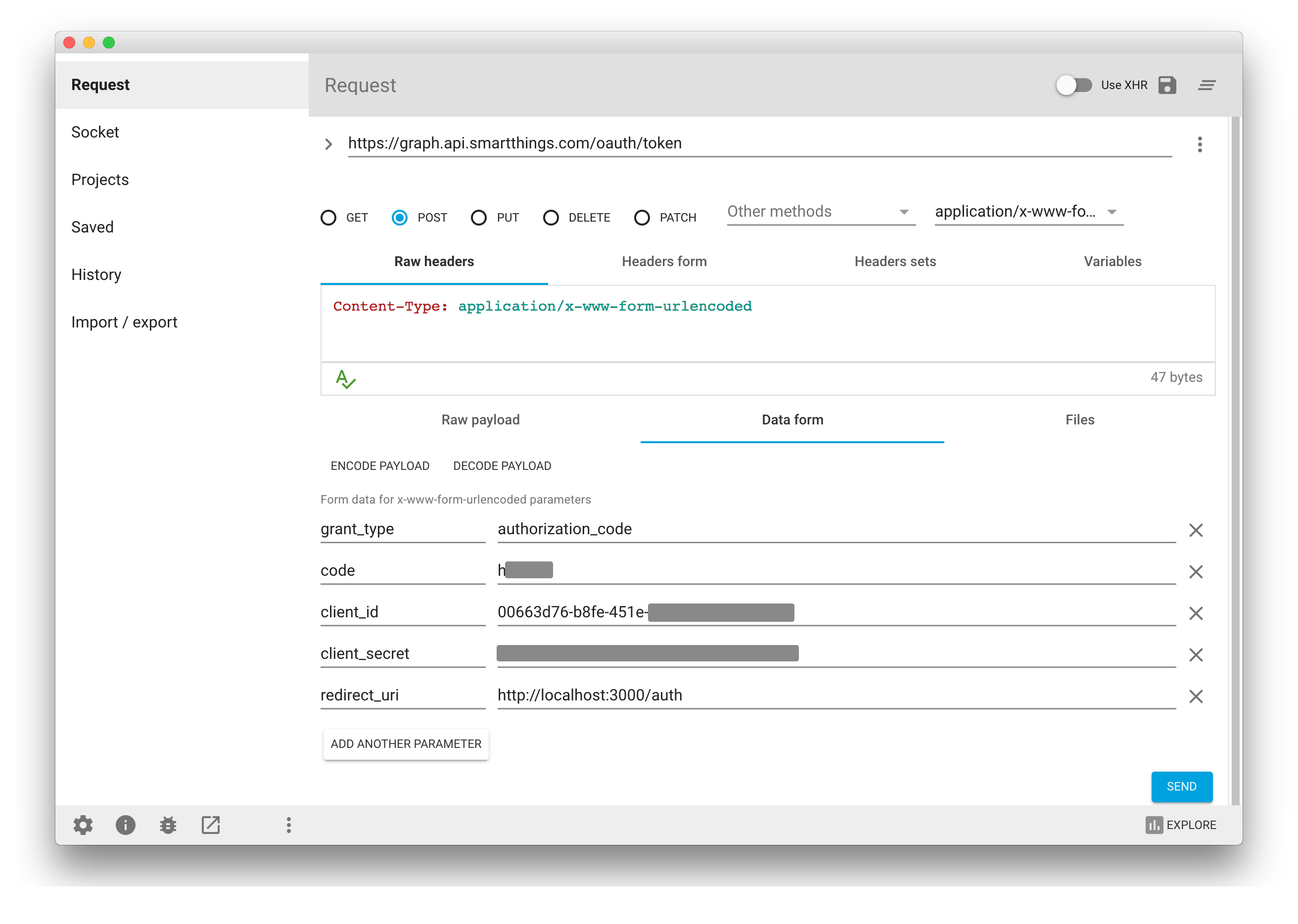
Now that you've got the code, it's time to make a POST request to get the access token. For this I like to use Advanced REST Client Chrome app. You can use any tool that can create a POST request with form parameters. Just fill in the fields as shown:
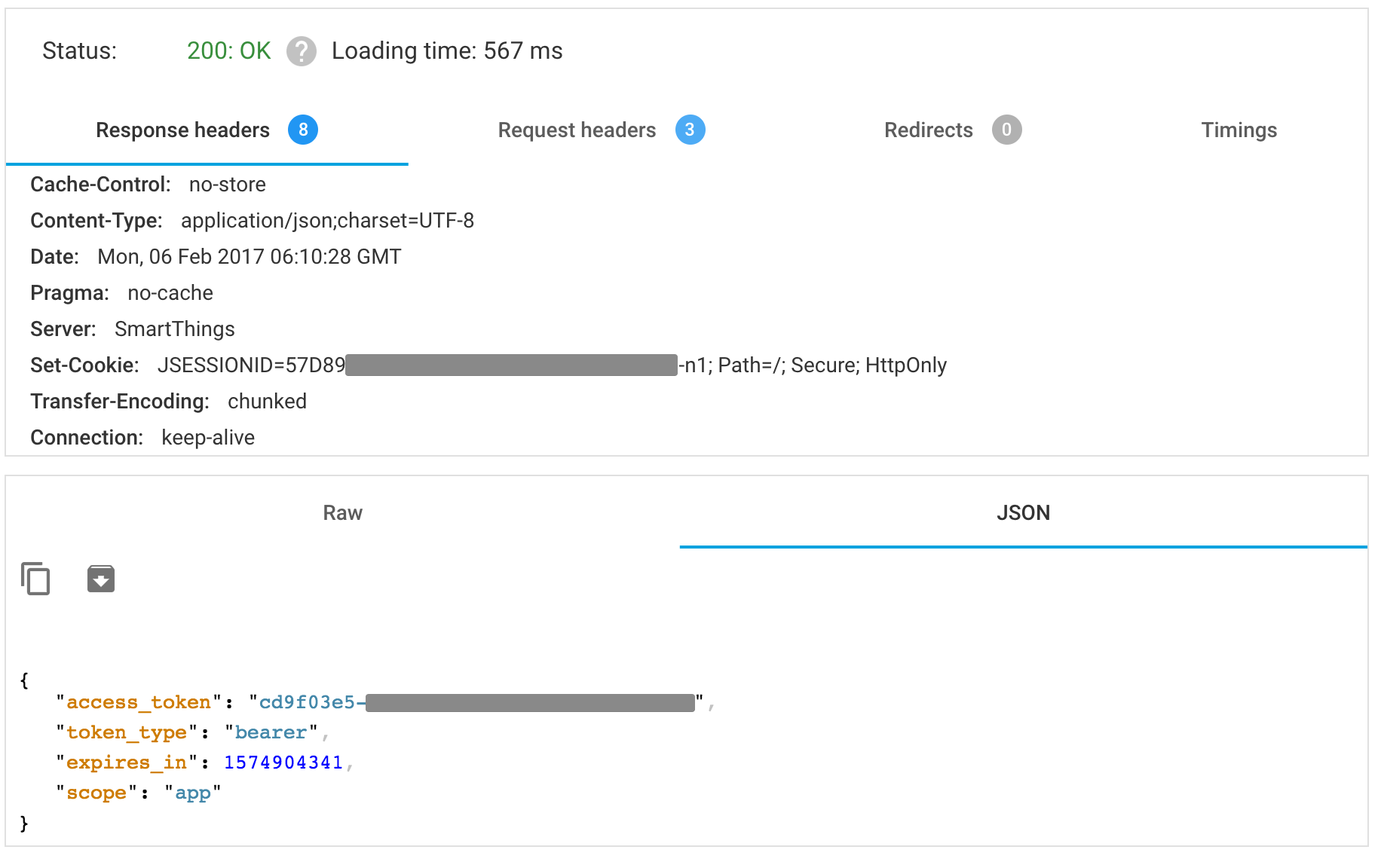
- Click Send, and with any luck, you'll get a successful response back that contains your access token:
Copy this access token into the credentials.lua file.
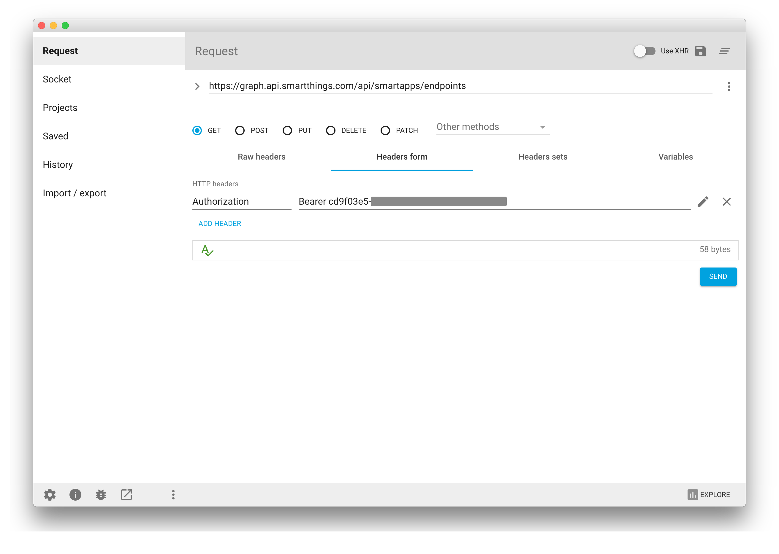
- Finally, get your SmartApp endpoint by doing a GET request to
https://graph.api.smartthings.com/api/smartapps/endpoints, signing the request with anAuthorizationheader and your token:
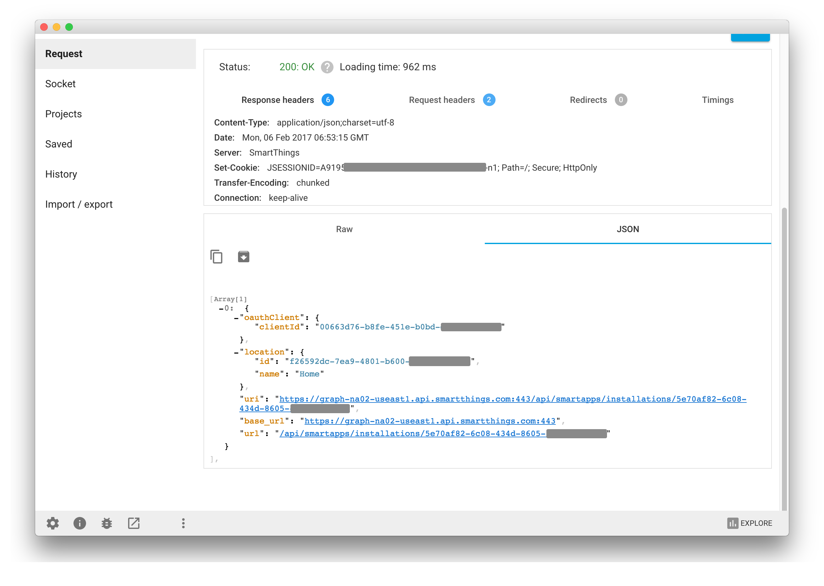
- Click send and make note of the url data returned:
Copy the base_url field from here into the apiHost variable in the variables file
Copy the url field into the apiEndpoint variable in the variables file
6. Flash the NodeMCU Lua firmware
Drivers
Windows and Mac users will need to download drivers so your computer can talk to the ESP8266 chip over USB. Depending on which board you have, there are different drivers:
Silicon LabsUSB to UART drivers for boards that:
- have the name Amica on the back
- the small component on the board near the USB port is engraved with SiLABS CP2102
WeMos CH340 drivers for boards that:
- have the name LoLin on the back or front
- the small rectangular component on the board near the USB port is engraved with CH340G
- Mac OS X Sierra users: use this driver
Firmware
-
The firmware contained in this repo is a recent build from https://nodemcu-build.com/ with following packages:
file,cjson,GPIO,HTTP,net,node,timer,UART,WiFiandTLS/SSL support. This firmware is on SDK version 1.5.4.1. Between the time that I did this project and wrote up this README, the NodeMCU firmware team has released a 2.0.0 firmware which has a bug with SSL/TLS and this program doesn't work. Until this is fixed, you must use the 1.5.4.1-final branch if you're building your own firmware at https://nodemcu-build.com/. More info in nodemcu/nodemcu-firmware#1707. -
I used esptool.py to flash the firmware (I'm using a Mac). There's pretty good documentation here including a couple other options for Windows users.
-
The exact command I used to flash the firmware is:
esptool.py --port=/dev/cu.SLAB_USBtoUART write_flash --flash_mode dio 0x00000 firmware/nodemcu-1.5.4.1-final-10-modules-2017-03-23-20-42-52-integer.bin
Your port may vary depending on your platform, OS and UART driver.
7. Load up the NodeMCU ESP8266
- Download Esplorer. It's a cross-platform IDE for interacting with the NodeMCU. Very handy.
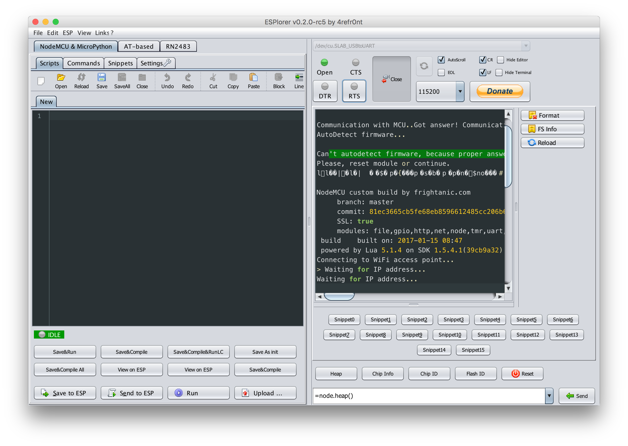
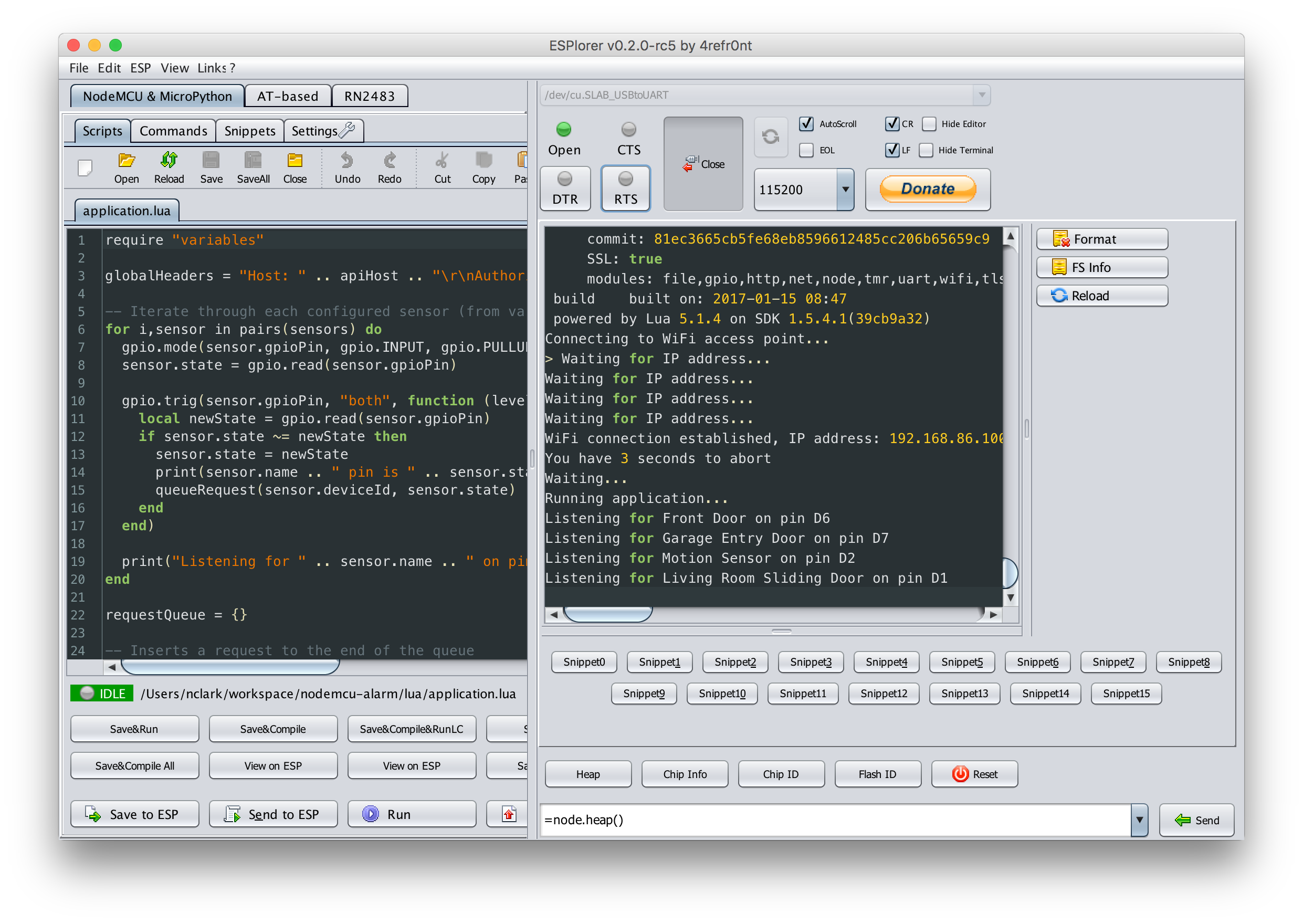
- Plug a microUSB cable into the NodeMCU and the other end into your computer, open up Esplorer, select the USBtoUART from the serial port chooser, set the baud rate to 115200, and click Open to connect. You may need to click the RTS button a couple times to connect and see something like this:
- Once connected, it's time to upload the code. Click Open in Esplorer and open each of the lua files on your computer and click "Save to ESP". Alternatively, you can use the Upload button to upload them all at once. This documentation was also very helpful in learning how to interact with the device using Esplorer.
- After all the code is uploaded, click the Reset button to restart the device. It should boot up, connect to your WiFi and output a message for each configured sensor, like this:
- Now let's test it out! The first sensor in this example is configured on pin 6 (labled D6). Take a wire and connect one end to pin D6 and the other end to the ground (GND). This completes the circuit, setting the pin low or 0, indicating that the contact sensor is closed. Hopefully it worked and you should see a success message in the Esplorer terminal, and when you open your SmartThings app you should see that the door is closed. Now remove the wire and watch it set to open.
- Note about the pins: I found that some of the pins don't work very well when normally low. It took a lot of trial and error to figure out that pins D1, D2, D6 and D7 worked reliabliy for me. I had problems with D3, D9 and D10. Your mileage may vary.
7. Connect your switches at the alarm panel
- Open up your alarm panel and find the cluster of wires coming from the switches throughout your house. Hopefully they're labeled well, otherwise you'll have some testing to do. Using some jumper cables, connect each pair of wires from each switch to the corresponding pin and ground on the board.
- Now go around your house testing it out!
- Once everything is working properly, you can plug the NodeMCU into a standard USB power adapter and it will automatically boot up, connect to WiFi, and start listening for switches.
8. Connect your siren and/or strobe (optional)
The SmartThings Alarm capability supports both a siren and a strobe state, so you can connect up to two wired devices to be controlled independently (they don't necessarily have to be a siren or a strobe). This is designed to integrate seamlessly with the Smart Home Monitor app and the Alert with Sirens function. My alarm system has a siren that activates with a 12V current from the alarm panel. You need a relay to switch the 12V power on with a 3.3V signal from the ESP8266 board. These instructions are written for the relay linked above, but should be similar for other relays.
- Connect the GND on the relay to the ground (-) on the ESP8266 board.
- Connect the VCC on the relay to a 3V3 output pin on the board.
- Connect the IN on the relay to the configured GPIO pin on the board, D1 for example.
- Connect the NO (Normally Open) on the relay to the red (+) wire going to your siren or strobe.
- Make sure the black (-) wire of the siren/strobe is connected to the ground (-) on the alarm panel.
- Connect the COM on the relay to the 12V aux power out (+) on the alarm panel with a jumper wire.
Problems or Questions
Please open an issue if you run into problems or have feature requests. You can also join the discussion on SmartThings community
