This repo is a fork of the original mixed-reality-robot-arm-control-demo repo. Here we added and changed some things for our 3D Vision course project. Please follow the Setup steps. The report is also in this repository report
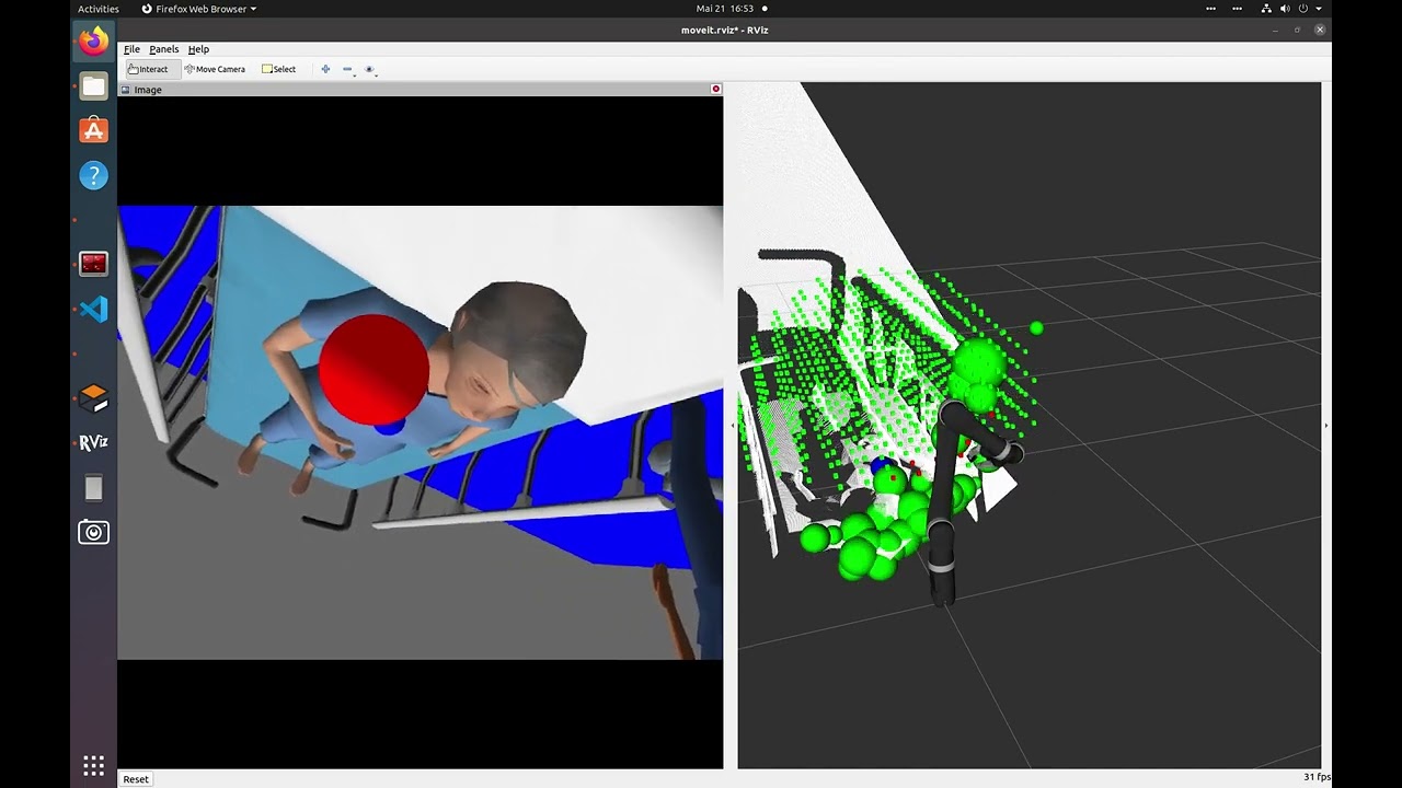
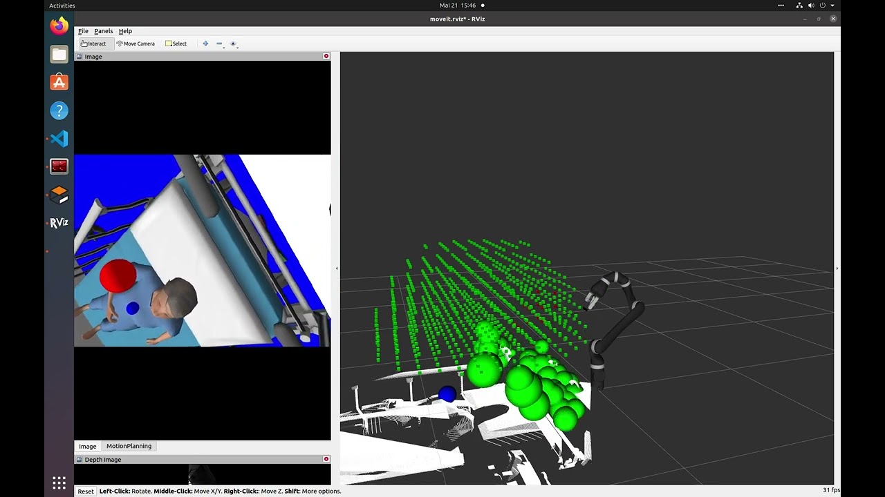
The first video uses the obstacle detection node while the second video shows the performance using the ground truth.
- Setup a ROS noetic workspace with following guide
- In the src/ folder of a new or existing catkin_ws, clone this repository
- Clone the following repositories into the same catkin_ws
cd ~/catkin_ws/src
git clone https://github.com/Divepit/kinova-ros.git
git clone https://github.com/Divepit/3d-vision-sugical-data-collection-interaction-package.git
git clone https://github.com/Divepit/3d-vision-sugical-data-collection-vision-package.git
- Make sure you have rosdep installed and configured and use it to install the required dependencies
cd ~/catkin_ws
rosdep install --from-paths src --ignore-src -r -y
- Run the following command to install missing dependencies for the controllers:
sudo apt-get install ros-noetic-moveit ros-noetic-trac-ik-kinematics-plugin ros-noetic-ros-control ros-noetic-ros-controllers

pip install -U scikit-learn

pip install numpy -U
Note: If the controller does not work the following package might help:
sudo apt-get install ros-noetic-pr2-arm-kinematics
-
Build and source the workspace with
catkin build && source devel/setup.bash. When building for the first time or after a clean please perform this step First Time Build -
You can now launch the Gazebo simulation using
roslaunch mrirac 3d_vision_project.launch.
In case the of problems please refer to Possibel Issues or check the Interaction Package README.
To easily call services, it is easiest if you use rqt. To install rqt use the following command:
sudo apt-get install ros-noetic-rqt-common-pluginsIn order to easily call services, first start the whole pipeline and once the rosmaster is running, open rqt as follows:
rosrun rqt_service_caller rqt_service_callerTo call the change_target_coordinate service and update the target coordinate, use the following command:
rosservice call /change_target_coordinate "{new_coordinate: {x: 4.0, y: 0.0, z: 1.75}}"Adjust the x, y, and z values as needed.
The service should respond with a success message, indicating that the target coordinate has been updated.
The node provides a service named /update_voxel_dome that allows you to update the parameters of the voxel dome. The service takes the following arguments:
radius(float64): The radius of the half-dome.voxel_count(int32): The number of voxels filling the half-dome.scaling_factor(float64): A factor to scale the size of the individual voxels. A value less than1.0will create space between the voxels.
The service returns a boolean success indicating if the operation was successful and a message providing additional information about the result.
After starting the Voxel Dome Generator node, you can call the /update_voxel_dome service using the rosservice command-line tool. Here's an example:
rosservice call /update_voxel_dome "radius: 2.0
voxel_count: 200
scaling_factor: 0.9"
This command updates the voxel dome's radius to 2.0, the number of voxels to 200, and sets the scaling factor to 0.9, which will result in smaller voxels with more space between them.
You can adjust these values as needed to generate a voxel dome with the desired size and density.
Four different obstacle behaviours can be set in the config.yaml file:
use_dynamic_obstacle: boolean

replan_trigger_obstacle: boolean
replan_trigger_interval: int [s]

replan_trigger_square: boolean
replan_trigger_square_bound_x: float
replan_trigger_square_bound_y: float
replan_trigger_square_offset_z: float- If all booleans are set to false, the obstacle locations can be changes using the
change_obstaclesservice. - If only
use_dynamic_obstacleis set to true, a sphere circling about the target is rendered into simulation. - If only
replan_trigger_obstacleis set to true, everyreplan_trigger_intervalseconds, an obstacle between the current camera and target position is rendered. - If only
replan_trigger_squareis set to true, a sphere will be renderedreplan_trigger_square_offset_zabove the target in a square with boundsreplan_trigger_square_bound_xandreplan_trigger_square_bound_y.
To change the obstacles, call the change_obstacles service with a list of Sphere messages. Here's an example of how to call the service using the rosservice command-line tool:
rosservice call /change_obstacles "obstacles: {spheres: [{center: {x: 2.0, y: 0.0, z: 1.0}, radius: 0.125}, {center: {x: 2.0, y: 1.0, z: 1.0}, radius: 0.125}]}"This command updates the list of obstacles with two spheres. The first sphere has its center at (2.0, 0.0, 1.0) and a radius of 0.125. The second sphere has its center at (2.0, 1.0, 1.0) and a radius of 0.125.
You can also change the obstacles programmatically in another ROS node by creating a client for the change_obstacles service and sending the new list of spheres.
install VSCode extension ROS (id: ms-iot.vscode-ros)
in the .vscode folder create a launch.json file and add following code:
{
    // Use IntelliSense to learn about possible attributes.
    // Hover to view descriptions of existing attributes.
    // For more information, visit: https://go.microsoft.com/fwlink/?linkid=830387
    "version": "0.2.0",
    "configurations": [

        {
            "name": "ROS: Attach",
            "request": "attach",
            "type": "ros"
        }
    ]
 }
ROS has to be running to start debugging.
open the Run and Debug menue and run "ROS: Attach". Select the language and the process you want to debug
Additional information under: https://github.com/ms-iot/vscode-ros/blob/master/doc/debug-support.md#launch
The following error can appear when running catkin build and using different python versions:
Errors     << catkin_tools_prebuild:cmake /home/colin/3dVision/visionPipeline/logs/catkin_tools_prebuild/build.cmake.000.log
CMake Error at /opt/ros/noetic/share/catkin/cmake/empy.cmake:30 (message):
  Unable to find either executable 'empy' or Python module 'em'...  try
  installing the package 'python3-empy'
Call Stack (most recent call first):
  /opt/ros/noetic/share/catkin/cmake/all.cmake:164 (include)
  /opt/ros/noetic/share/catkin/cmake/catkinConfig.cmake:20 (include)
  CMakeLists.txt:4 (find_package)
The following build flag may solve the problem:
catkin build -DPYTHON_EXECUTABLE=/usr/bin/python3 -DPYTHON_INCLUDE_DIR=/usr/include/python3.7m
If an error like the following appears when running catkin build:
fatal error: sdc_interaction/UpdateVoxelDome.h: No such file or directory
    5 | #include <sdc_interaction/UpdateVoxelDome.h>
It is necessary to go into the file CMakeLists.txt and comment out the following two lines:
add_executable(voxel_dome_generator_node src/voxel_dome_generator_node.cpp)
target_link_libraries(voxel_dome_generator_node ${catkin_LIBRARIES})
Once they are commented out, run catkin build again. If it is successful, uncomment the two lines again and re-run catkin build. There was no better fix found for this so far.
The launchfile used for our project can be accessed as follows:
roslaunch mrirac 3d_vision_project.launchThe launchfile simply launches the old launchfiles which have been used in the original mixed-reality-robot-arm-control-demo repo as well as our new launchfiles for the vision and interaction packages.
Create in the workspace folder a NAME.sh file and paste the following lines into it
#!/bin/bash

catkin build
source devel/setup.bash
roslaunch mrirac 3d_vision_project.launch
Launch the script with
bash NAME.sh
Programming industrial robot arms can be a tedious and unintuitive process with conventional control methods, such as joysticks or 2D GUIs.
This repository contains both a Unity application and ROS packages that enable users to control a Kinova Jaco 2 robot arm using the Microsoft HoloLens 2 through a Mixed Reality experience. Besides being able to intuitively set pose targets for the robot directly in task space, there is also a demonstration for planning a simple pick and place task. Furthermore, the application utilizes the spatial awareness capabilities of the HoloLens 2 to provide information on obstacles that are in the robot workspace, enabling collision-aware motion planning of robot movements.
Required hardware:
- Kinova Jaco 2 Robot
- Microsoft HoloLens 2
- External PC (Ubuntu 20.04)
- Printed QR codes for robot localization and object detection
- Mount the robot securely to a flat surface
- Connect the power cable and the controller to the robot
- Power on the robot and send the arm to the home position by holding the middle button on the controller
Make sure the HoloLens 2 device is in developer mode. This is required in order to deploy the Unity application to the device.
As the robot arm does not have an internal computer capable of running the ROS components, a separate machine is required. This machine can be anything capable of running Ubuntu 20.04, such as an Intel NUC or a laptop. Note that running WSL2 on Windows also works but to our knowledge only when using the Kinova Arm in the Gazebo simulation. The Kinova Ethernet/USB integration to WSL is non-trivial though.
Connect the Ethernet cable to the port on the robot and to a port on the PC. So that the PC can connect to the robot driver via the Ethernet connection, the wired connection has to be configured in the following way:

This project was developed using ROS Noetic. It may work with other ROS releases, but it is recommended to set up a Noetic environment on the external PC, using these instructions.
Print out the QR codes used for robot and object localization. Generally, the detection improves with increased QR code size.
Place the QR code for robot localization on the flat surface that the robot is fixed to. When starting the application for the first time, detect the QR code by looking directly at it and the robot model should appear next to it. Move the QR code until the holographic robot model lines up with the real robot. You can then fix the QR code to the surface with tape.
The object used for the Pick and Place demo also requires a QR code to be attached, so that the HoloLens can localize it. The object used in the demo videos is a cylinder with a diameter of 7.5cm and a height of 13cm. Attach the QR code to the top of the cylinder as centrally as possible.
- Clone this repository and open the MRIRAC_Unity folder from the Unity Hub (tested with Unity 2020.3.40f1 - we suggest using this exact Unity version, as version up/down-grades sometimes break Unity projects)
- In the Unity editor, open the ROS Settings from the Robotics menu and set the ROS IP Address to the IP of the external machine connected to the robot arm.
- Build and deploy the application to your HoloLens 2 device, following these instructions
- In the src/ folder of a new or existing catkin_ws, clone this repository
- Clone the following repositories into the same catkin_ws
cd ~/catkin_ws/src
git clone https://github.com/Divepit/kinova-ros.git
git clone https://github.com/Unity-Technologies/ROS-TCP-Endpoint.git
- Open
kinova-ros/kinova_bringup/launch/config/robot_parameters.yamlin your favorite text editor, and change theconnection_typeparameter fromUSBtoEthernet(line 13) - Make sure you have rosdep installed and configured and use it to install the required dependencies
cd ~/catkin_ws
rosdep install --from-paths src --ignore-src -r -y
- Run the following command to install missing dependencies for the controllers:
sudo apt-get install ros-noetic-moveit ros-noetic-trac-ik-kinematics-plugin ros-noetic-ros-control ros-noetic-ros-controllers

pip install -U scikit-learn

pip install numpy -U
Note: If the controller does not work the following package might help:
sudo apt-get install ros-noetic-pr2-arm-kinematics
- Build and source the workspace with
catkin build && source devel/setup.bash - Test the setup by running
roslaunch mrirac kinova_real.launchor alternatively (if you don't have a Kinova arm available or setup) you can launch the Gazebo simulation usingbash MRIRAC_ROS/mrirac/launch_sim.bash.
If the robot is connected correctly and the setup was successful, you should be able to set a pose goal using the rviz interface and the robot will move to that position once plan and execute is pressed.
install VSCode extension ROS (id: ms-iot.vscode-ros)
in the .vscode folder create a launch.json file and add following code:
{
    // Use IntelliSense to learn about possible attributes.
    // Hover to view descriptions of existing attributes.
    // For more information, visit: https://go.microsoft.com/fwlink/?linkid=830387
    "version": "0.2.0",
    "configurations": [

        {
            "name": "ROS: Attach",
            "request": "attach",
            "type": "ros"
        }
    ]
 }
ROS has to be running to start debugging.
open the Run and Debug menue and run "ROS: Attach". Select the language and the process you want to debug
Additional information under: https://github.com/ms-iot/vscode-ros/blob/master/doc/debug-support.md#launch
The following error can appear when running catkin build and using different python versions:
Errors     << catkin_tools_prebuild:cmake /home/colin/3dVision/visionPipeline/logs/catkin_tools_prebuild/build.cmake.000.log
CMake Error at /opt/ros/noetic/share/catkin/cmake/empy.cmake:30 (message):
  Unable to find either executable 'empy' or Python module 'em'...  try
  installing the package 'python3-empy'
Call Stack (most recent call first):
  /opt/ros/noetic/share/catkin/cmake/all.cmake:164 (include)
  /opt/ros/noetic/share/catkin/cmake/catkinConfig.cmake:20 (include)
  CMakeLists.txt:4 (find_package)
The following build flag may solve the problem:
catkin build -DPYTHON_EXECUTABLE=/usr/bin/python3 -DPYTHON_INCLUDE_DIR=/usr/include/python3.7m
This section aims to provide a brief guide on how to use the core functions of the Mixed Reality experience.
A collection of demonstrations is available here: https://youtube.com/playlist?list=PLihM5VMGCK942veA_fDujf4P7h3gCeHFv
Start the ROS components:
roslaunch mrirac kinova_real.launch
From the Application Menu, start the MRIRAC app

- Home Arm: Send arm to 'Home' position
- Summon Target: Summon pose target hologram
- Trajectory Lines: Toggle display of trajectory lines
- Obstacles: Open Collision Obstacle UI
- Show Mesh: Toggle display of spatial awareness mesh
- Pick and Place: Open Pick and Place UI
SendRobotToPose.mp4

- Sphere: Instantiate a spherical hologram obstacle
- Cube: Instantiate a cubic hologram obstacle
- Cylinder: Instantiate a cylindrical hologram obstacle
- Clear Obstacles: Remove all obstacles from the planning scene
- Toggle Spatial Obstacles: Toggle transmission of spatial awareness mesh information
HolographicObstacleAvoidance.mp4
SpatialObstacleAvoidance.mp4

- Plan Pick and Place: Plan pick and place mission
- Execute Pick and Place: Execute planned pick and place mission
- Reset: Reset detection of pick target (removes added obstacle)
PickAndPlaceDemo.mp4
This project was developed as part of the Semester Thesis for my (Matthew Hanlon) MSc. Robotics, Systems and Control at ETH Zurich. The project was supervised by Eric Vollenweider (Microsoft Mixed Reality and AI Lab Zurich), in collaboration with the Computer Vision and Geometry Group.
Trademarks This project may contain trademarks or logos for projects, products, or services. Authorized use of Microsoft trademarks or logos is subject to and must follow Microsoft’s Trademark & Brand Guidelines. Use of Microsoft trademarks or logos in modified versions of this project must not cause confusion or imply Microsoft sponsorship. Any use of third-party trademarks or logos are subject to those third-party’s policies.