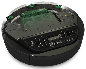
Create an autonomous robot machine using a finite state machine (FSM) to avoid obstacles:
- The robot starts motionless, and starts its behavior when a button on the robot is pressed.
- The robot advances until it finds an obstacle less than one meter in front of it.
- When it finds an obstacle, the robot turns 90 degrees, and goes around the obstacle in an arc-shaped movement.
- If while you are making the arc, you find a new obstacle, do the same thing from point 3 again.
-
First of all, we need Ubuntu. It is a Linux Debian-based operating system, A.K.A Linux Distro. We are working with the 22.04 Jammy Jellyfish 🪼 version. You might be already familiar with it, however here you have a step-by-step tutorial on how to install it on your machine.
-
ROS. ROS stands for Robot Operating System, and it is the middleware that the vast majority of robots out there use nowadays, and so are we! We are focusing on the latest stable release, which is ROS 2 Humble Hawksbill 🐢. From there you can navigate through all the documentation, but here is a shorcut to the installation page.
FUN FACT
Did you know that every ROS distribution is named alphabetically? Not only that, but it is always a turtle species which starts with the current letter. Hawksbill is the colloquial name for the turtle species Eretmochelys imbricata. Here you can learn more about this animal if you feel curious!
- ir_robots package. Intelligent Robotics Lab is research group from the Universidad Rey Juan Carlos. They have developed the package with all the dependencies you will need, among some other things, like a simulator setup with Gazebo. You can find the installation steps on their README, check it out!
Once you have those three steps, using this package is a piece of cake in comparison!
First of all, you need to source both your ROS installation and your workspace.
source /opt/ros/<ros-distro>/setup.bash
source <your-workspace-path>/install/setup.bash
PRO TIP: You can include those lines on your
.bashrcso every new terminal will have this work already done.
Then you can move to your workspace.
cd <your-workspace-path>From there, you should build the packages. If this if your first time you will probably need to build every package:
colcon build --symlink-installBut remeber that you can always select which packages are going to be built:
colcon build --symlink-install --packages-select avoid_obstacle_cppOnce finished, you can connect to your Kobuki like so:
ros2 launch ir_robots kobuki.launch.pyYou will know if the connection was successful because you will hear a welcoming jingle from the robot!
Now open a new terminal. The last command should have blocked the terminal we were using. Remeber to source again if you did not add those commands to your .bashrc. Finally we can launch the avoid_obstacle_cpp package like so:
ros2 launch avoid_obstacle_cpp avoid_obstacle.launch.pyEvery man for himself! The robot is finally running the program!
PRO TIP: From this point, we highly recommend to take cover if you do not trust the authors of this package.
To get hands-on with this practice, the first thing we did was sketch a state diagram in which you could see at a glance the different states through which the robot would go through in its operation. Later we thought that in order for the practice to be more complete, we could add some more things that would provide the robot with better functioning in addition to what was already requested.
-
Bumper: To make the detection of the robot as accurate as possible we decided to take readings from the bumper because the laser only detects things that are at the same height as it, but does not detect anything shorter than it. For this reason, we helped with the bumper because it could detect any object that the laser does not capture below it. When the robot collides with an undetected object, it moves back a few meters and begins to move in an arc to try to avoid the obstacle as if it had been detected by the laser.
-
Wheel drop: We also decided to add the wheel drop topic to know when the robot is in the air because a person has lifted it. When it is detected that the wheels have been lifted, it stops walking and returns to the start state. This allows a greater handling of the robot in unexpected situations.
-
Leds and sounds: To make it easier and more comfortable to debug the robot's status, we decided to add colored leds and sounds to indicate what it is going on inside the robot at all times. For example, when the robot changes state, it emits a certain sound and when the robot detects an unexpected object, the led turns red.
-
New node: In order to cut our teeth in the multi-node scope, we decided to implement a whole node in charge of the LIDAR Feedback. This allowed us to check anytime if the robot is actually detecting an obstacle. Even if the robot is not moving or not executing the main node. We could have done this in the main node, but it woyld have been mandatory to have a procedure in the control cycle that takes charge of the led publisher as well as the LIDAR readings. Since this would probably be a separate method anyway, it made sense to us to fully isolate this feature on it's own node.
RQT returns this final diagram after all implementations:
However, we are explaining how we developed the whole application from the very beginning. Changes are noticeable! Let's start with the state diagram:
This was the first sketch we did and as you can see there are five states: stopped, go forward, obstacle turn, arc turn, turn exit.
Since we decided to create new features and new states, we had to restructure the state diagram. Some of the states were renamed and others created from scratch. In addition, the Lidar node was added with the leds apart from the main node.
We also made a sketch of the node diagram, this was our first approach:
We have also created a node diagram to better illustrate how everything works inside once all the features were finally finished:
- The multi-case
switch. Check this snippet:
void
AvoidObstacleNode::change_status_led(int new_state)
{
  kobuki_ros_interfaces::msg::Led out_led;

  /*
   * The message is manipulated depending on the state that is
   * parsed. Some of them could have the same output, and thus the order matters.
   * This order may differ on the numerical order they have been defined.
   *
   * Then, whatever message was built, it is published.
   */

  switch (new_state) {
    case READY:
      out_led.value = kobuki_ros_interfaces::msg::Led::ORANGE;
      break;
    case BACK:
    case STOP:
    case EMERGENCY_STOP:
      out_led.value = kobuki_ros_interfaces::msg::Led::RED;
      break;
    case FORWARD:
    case YAW_TURN_IN:
    case YAW_TURN_OUT:
    case DODGE_TURN:
      out_led.value = kobuki_ros_interfaces::msg::Led::GREEN;
      break;
    /*
     * There may be cases in which you do not want to update
     * anything, so the method will return without publish anything.
     * Any other case should be contemplated on the switch statement.
     */
    default:
      return;
  }

  led_pub_->publish(out_led);
}
There is a similar method to manipulate the sound. They both are called whenever the state of the robot is changed. Although the comments already provide an explanation, it is worth noting the lack of break on some of the cases of the switch. With this we are "merging" all of the consecutive cases together, meaning that they will all behave identically. The cases whose outputs will be identical, should be sorted this way to avoid code duplication. Any other cases not considered above will not update the state of the led. Same goes for the sound, since it is managed in an identical way. Cool!
-
Grip change: During the practice we realized that the robot did not walk the same on the hard floor as it did on the carpet. This is due to the fact that the different kinds of flooring have different friction and influence the movement of the robot to a greater or lesser extent. This causes the robot to not be able to perform the turns well in some cases.
-
Sensor remaping: For the correct functioning of the robot and its correct implementation, we decided to remap the topics as can be seen in the
avoid_obstacle.launch.pyfile.
 remappings=[
            ('input_scan', '/scan_filtered'),
            ('output_vel', '/cmd_vel'),
            ('input_button', '/events/button'),
            ('lidar_led', '/commands/led2'),
            ('status_led', '/commands/led1'),
            ('output_sound', '/commands/sound'),
            ('input_bumper', '/events/bumper'),
            ('input_wheel_drop', '/events/wheel_drop')
]- Parameters in
params.yaml: Also, we put all the parameters that the robot uses to work in a file calledparams.yaml. From this file you can easily configure the parameters such as the speed, the angle of rotation, the distance to the obstacle...
lidar_led_feedback:
  ros__parameters:
    obstacle_distance: 1.0

avoid_obstacle:
  ros__parameters:
    yaw_time: 2.5
    back_time: 1.0
    dodge_time: 13.0
    scan_timeout: 1.0
    speed_linear: 0.3
    speed_angular: 0.9
    speed_linear_factor: 0.8
    speed_angular_factor: 0.4
obstacle_distance: 1.0-
Continous Integration (CI) setup. We have added a workflow to be triggered through GitHub Actions whenever a
pull requestis made. From this workflow, the code is built and tested in any enviroement we want1. You can find this workflow here. With this feature we can automatically test our code before pushing it to themainbranch. This allows us to directly review thepull requestwithout worrying about breaking the already pushed code, coding style... Since we will instantly see a checkmark with the test output. A further step that can be taken is to make this test to trigger another workflow that makes our work easier, like automatically deploy our packet! A.K.A. Continous Deployment (CD).In order to tackle this, we have followed this article from the Ubuntu blog itself. There you can find more details about how exactly the workflow file actually works!
Before launching the program in the real robot, we have tested it beforehand in a simulated enviroment, using tools like Gazebo or RViz. Although it does not behave like a real robot would, it is close enough to debug or improve the code. Here you can see a representation of the test we have done during the development of this exercise:
avoiddemosim.mp4
NOTE:
The simulation video is large. GitHub did not like that, so there might be problems when reproducing it. You can find it here in the repo, and this is a link to the video hosted on YouTube. Sorry for the inconvenience!
In order to simulate physical inputs, like a button or the bumper, we acted like a node publishing messages to the appropriate topic. On the other hand, we can also subscribe to the topics where the robot will publish feedback, like the leds or the sound, so we can keep track of this robot behavior section.
We have noticed that the speed of the simulated robot can be completely different to that of the real robot (Thus the apparently erratic behaviour of the robot in the simulation). However, thanks to the params.yaml file, we can quickly change these values at will before each execution without having to recompile the code.
Below you can see some demos about the features we have described earlier:
-
Lidar Feedback. Notice how the
STATUS_LEDfrom the robot (Which is the middle one) staysORANGE(Which means that the main node is waiting for a button to be pressed) while the right led reacts to the LIDAR readings: -
Bumper feature:
-
Wheel Drop feature:
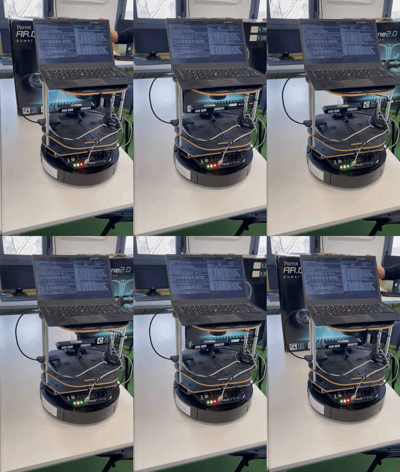
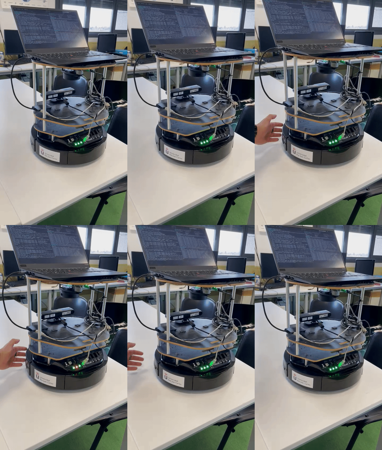
Below you can see the application running with no issues at all:
real_case.mp4
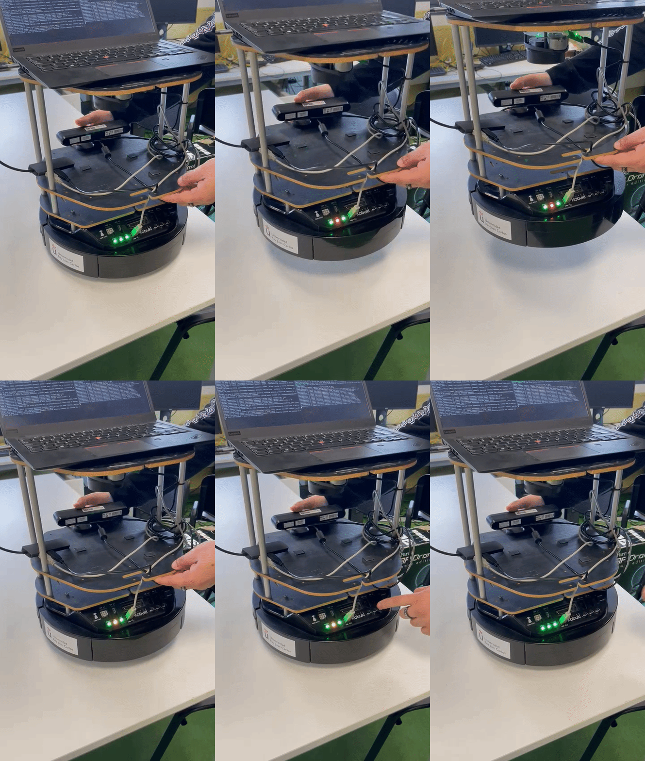
Here you can see a real case where the bumper was pressed and the robot itself being lifted intentionally to trigger the EMERGENCY_STOP state:
real_case_bumper.mp4
Notice how, although both events (Bumper and Wheel Drop) trigger the same state, the robot behaves differently depending on which one actually happened. This decision was made due to some procedures that must take place in every kind of "emergency", like stopping the robot from moving and, perhaps, publishing the issue in a topic... Later we can actually manage what caused the issue once we know we have everything under control.
This is a project made by the StressOverflow, a student group from the Universidad Rey Juan Carlos. Copyright © 2023.
Maintainers:
This work is licensed under a APACHE LICENSE, VERSION 2.0.
Footnotes
-
In this case, Ubuntu 22.04 Jammy Jellyfish and ROS 2 Humble Hawskbill, which is the same enviroment we are working with. ↩


