We will be using the ESP32 DevkitC V4 board in this class. One will be provided for you. If you blow it up (it happens) they’re available in the TIW vending machine for $5. Documentation for the specific board we're using is here. This lab will be done individually. You will clone the assignment from the class Github, add your code, answer the questions in Report.md, and push it when you’re done.
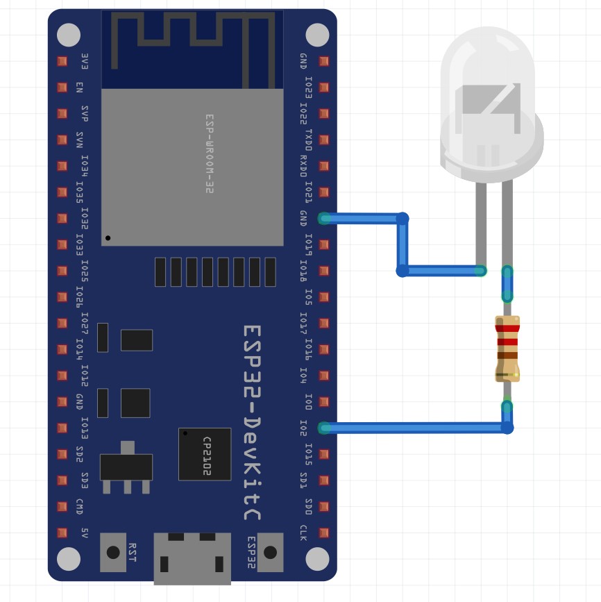
 Note: Whenever I refer to a pin number in this document, I am referring to the GPIO pin, shown in brown.
Git can be a little tricky to get the hang of, but it is extremely useful and will make your life a lot easier going forward, especially for group projects. The most important commands are clone, add, status, commit, push, and pull. You can find a nice cheat sheet here or in Git.md. If you have questions, Google it first, post the questions on Piazza, then ask questions in office hours.
- Create a Github account and log in. Use your utexas email so you can get the free github education benefits.
- Accept the assignment link from the Canvas announcement. Link your Github account to your EID.
- Install git on your computer following the instructions at git-scm
- Once you have Git installed, you can clone the lab 1 repo to your computer. Use the
git cloneGit Bash (Windows), or your terminal (Linux, MacOS) to clone the repo wherever you want. I recommend making a folder to put all your repos for this class. - Set up an SSH key with your github account so you don’t have to type in your password all the time. Follow the Github SSH tutorial here
- Download and install the Arduino IDE. When you open the IDE you should see a blank sketch with a setup function and a loop function. Why do embedded systems need a setup and a loop? Note: Depending on your OS/Arduino IDE version, you may need to install the CP210x USB to UART Bridge Driver separately. If you can't flash your board, try this.
- Since we are using ESP32, which is not in the default Arduino options, we need to download the board files. Go to File > Preferences > Additional Board Manager URLs and add
https://dl.espressif.com/dl/package_esp32_index.jsonto the list. - Now you can tell the Arduino IDE you’re using and ESP32. Go to Tools > Board > Board Manager and search for ESP32. Install the ESP32 package. Install version 1.0.3. Then go back to Tools > Board and select ESP32 Dev Module from the dropdown.
- Connect the provided 220 Ohm resistor and blue LED to GPIO 2, as shown in the diagram. (Hint: The side with the big flag is the cathode (-), the side with the little triangle is the anode (+). Now you can clip your LEDs and never worry about the polarization again!)
- Connect your board to your computer using a micro USB cable. Go to Tools > Port and select the COM port for your connected board.
- Try programming the board. Open the examples/Blinky sketch. In the toolbar at the top, you’ll see a check mark and an arrow. If the code is not compiled, clicking the arrow will first compile the code, then program the board. You should now see the onboard LED blinking. IMPORTANT: If you are using a TIW ESP32, You cannot program it unless you hold down the boot button (to the right of the USB port) the entire time its flashing. There is a hardware fix for this, if you want to implement it on a breadboard or PCB you can follow this tutorial here: Solve failed to connect to ESP32 (optional)

Saleae is a company that produces industry standard logic analyzers. Their software is excellent, user friendly, and compatible with the mini logic analyzers provided to your team. When you outgrow the provided mini logic analyzer (it can only sample at up to 24MHz, you will need more one day) I highly recommend investing in a Saleae, both because their analyzers are excellent, and to support their Software/R&D. Download the software here.
- Connect your logic analyzer using Mini USB.
- Connect the ground wire from your logic analyzer to the ground pin on the ESP32. Why do you need to do this? Think back to EE302.
- Open the Saleae software. It should detect the logic analyzer automatically. Play around with the interface. Add some channels. Change the sampling speed. Try the trigger buttons. Saleae has excellent tutorials here.
- Create a new sketch inside your repo that you cloned. Name it Lab1_Blink. After creating the sketch, use
git add *to add the sketch folder and files. You can check that they’re being tracked usinggit status. - Copy the setup code directly from Blinky.ino in the examples folder. Copy the code from the example's loop into a new function called timedBlink. Put this new function in the space between setup and loop. Use this code to obtain the same result as before. You’ll need to change the code in the loop to call this new function, and you’ll need to pass the function a number for the parameter "interval". Hint: you only need 1 line of code in the loop.
- Once you've confirmed your new blink works, edit the loop again so that the board blinks with this sequence: 0.25 second on, 0.25 off, 0.5 on, 0.5 off, 1 on, 1 off, repeat. Connect your logic analyzer to pin 2 and take a screenshot of this sequence on Saleae. Save the image to your repo in the img folder and link to it in your
Report.md. - At this point, commit your changes. Navigate to your repo in the command line of your choice, or open Git Bash inside your repo. The commands are:
git add img/*
git add Lab1_Blink/*
git commit -am "Wrote timedBlink function"
git push- Check your repo on Github. You should be able to see your newest changes and commit message.
- Add another function to your sketch. This function will dim the light to create a fading effect. Use this code:
void dimmer(int freq, int duty) {
  int period, onTime, offTime;
  period = 1000/freq;
  onTime = period * duty / 100;
  offTime = period - onTime;
  digitalWrite(LED_BUILTIN, HIGH);
  delay(onTime);
  digitalWrite(LED_BUILTIN, LOW);
  delay(offTime);
}- Replace the timedBlink function call in the loop. Use for loops to count up and down and calls the dimmer code every iteration with a new duty value. Set the frequency to 100. Connect your logic analyzer to pin 2 and observe the fading effect signal. Take a screenshot for your
Report.md. - Now, reduce the frequency (starting at 100Hz) in 10Hz increments by changing the freq argument when you call the function. Observe the unwanted behavior. What is going wrong? Brainstorm some solutions. Dimmers exist in the real world. What is their solution?
- When you’re done, commit your new code and push.
Communication is essential when building anything electronic. Many transducers and chips out there must be connected to your microcontroller using a communication protocol. The three most common are Universal Asynchronous Receiver/Transmitter (UART), Serial Peripheral Interface (SPI), and Inter-Integrated Circuit (I2C, aka Wire). In this section, you will observe how UART and SPI protocols work on your logic analyzer and serial monitor. I2C requires an external device to test, so you will not be observing it in this lab. Read the I2C_Example sketch, but do not run it, to answer the questions in Report.md. You do not need to write any code, just use the provided sketches. Type the same message (e.g. hello world) for each example, so you can compare the results.
UART, or Universal Asynchronous Receiver/Transmitter allows the ESP32 and your computer to communicate. You do not need to write any new code for this part. You will observe the communication on your logic analyzer and serial monitor.
- Open the UART_Example sketch included in this repo
- Open the library manager in Arduino IDE. Search for ESPSoftwareSerial. Install version 5.4.0. Do not install version 6+.
- Compile and flash your board. Once it’s done flashing, open the Serial Monitor (Tools > Serial Monitor)
- Connect two wires from your logic analyzer to pin 1 (TX0) and pin 3 (RX0)
- Put an edge trigger on RX in the Saleae software. Type a message in the serial monitor. Saleae should start sampling automatically. You should see pulses on both lines.
- Add a UART analyzer in the Saleae software. In the right hand panel, click the add analyzer button. Select Async Serial. Add one for both the RX and TX lines. You should be able to read your message! Take a screenshot for your
Report.md. - Use the Timing Marker Pair tool to profile how long it takes to send your message via UART. Include this value in your
Report.md
SPI, or Serial Peripheral Interface, is a very fast and robust synchronous communication protocol. However, it requires more wires than UART and I2C. It is used to connect "master" devices to "slave" devices. Each direction of communication has it's own line. There is Master Out Slave IN (MOSI) and Master In Slave Out (MISO). There is also a clock line and usually a chip select (CS, aka slave select or SS) line to tell the master and slave when to be listening, making this protocol less sensitive to noise. Not all peripherals require a chip select line, or have a way of responding, so the two most commonly used lines are MOSI and CLK.
- Open the SPI_Example sketch included in this repo.
- Connect your logic analyzer to ESP32 pins 23 (MOSI), 18 (CLK) and 5 (CS). MISO is unused in this example.
- Add a SPI analyzer in Saleae. Select the channels you connected to each pin, and leave the rest of the settings as default.
- Put a falling edge trigger on the CS channel and click Start
- Type a message in the Arduino Serial Monitor. Saleae should start sampling automatically.
- You should be able to see the pulses and decoded value for your message. Take a screenshot for your
Report.md. - Use the Timing Marker Pair tool to profile how long it takes to send your message via SPI. Include this value in your
Report.md.
Deliverables: Answer the questions in Report.md, and include all Arduino sketches.