Flash memory is a non-volatile memory widely used for data storage in various electronic devices. Its construction involves floating-Gate Transistors, enabling it to retain data even when power is off.
To erase and write data on flash memory, we need to apply a high voltage to each cell. To provide this high voltage, a flash memory controller (or driver) is required.
1.2.1. Programming (Writing Data):
- To write data to flash memory, a high voltage is applied to the control gate of the floating-gate transistor.
- This causes electrons to tunnel through the insulating layer and get trapped in the floating gate, altering the cell's threshold voltage to represent binary data.
1.2.2. Erasing:
- To erase data, a high voltage with the opposite polarity is applied.
- This causes electrons to tunnel out of the floating gate, resetting the cell to its default state (usually all 1s).
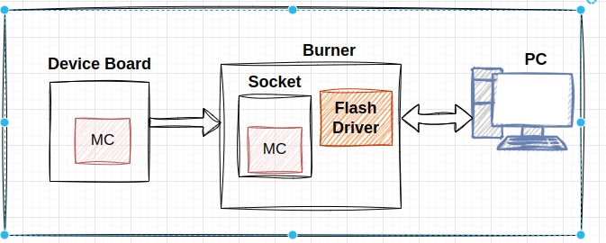
It involves programming the micro-controller or memory chip outside of its circuit, commonly used during manufacturing or before the chip is soldered onto the circuit board.
2.1.1. Advantages:
- Isolation: Reduced risk of interference or errors.
- Speed: High-speed programming with optimized connections and power supplies.
- Quality Control: Thorough testing and verification before installation.
2.1.2. Disadvantages:
- Time-Consuming: Removing and replacing the chip can be slow.
- Equipment: Requires specialized programming hardware and adapters.
2.1.3. Use Cases:
- Initial programming of micro-controllers or memory devices.
- Programming large batches of chips in production environments.
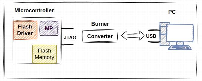
It allows the micro-controller or memory chip to be programmed while installed in its target circuit, used during development, production, and field updates.
2.2.1. Advantages:
- Convenience: Faster process without removing the chip.
- Flexibility: Enables updates and reprogramming without disassembly.
- Integration: Suitable for automated programming and testing in production lines.
2.2.2. Disadvantages:
- Accessibility: Requires access to programming pins or a dedicated interface.
- Power Supply: Requires a stable power supply from the target circuit.
2.2.3. Use Cases:
- Firmware updates during development.
- Final programming and calibration in production.
- Field updates and bug fixes.
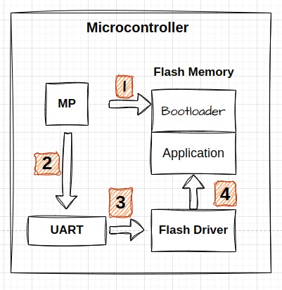
It enables the microcontroller or memory device to be reprogrammed while the application is running, ideal for field updates without interrupting the device's operation.
It is beneficial when dealing with many microcontrollers because each may require different programming protocols like JTAG, SPI, or I2C. To make updating new code easier, using a common communication protocol such as UART or CAN simplifies the process. This approach ensures smoother firmware updates across multiple devices, making management and maintenance more efficient in distributed systems.
2.3.1. Advantages:
- Non-Disruptive: The device continues to operate during updates.
- Remote Updates: Supports over-the-air (OTA) or remote updates, reducing the need for physical access.
- User-Friendly: End-users can perform updates without specialized equipment.
2.3.2. Disadvantages:
- Complexity: Must ensure updates do not interfere with operations or leave the device unusable if interrupted.
- Security: Requires robust measures to prevent unauthorized access and ensure update integrity.
- Memory Management: May need additional memory to store new firmware while the old one is running.
2.3.3. Use Cases:
- Firmware updates for IoT devices, consumer electronics, and automotive systems.
- Devices in remote or hard-to-access locations.
A bootloader is a small program responsible for initializing and loading the main operating system or firmware of a device when it is powered on or reset. In embedded systems, it plays a crucial role in starting up the device and ensuring that the correct software is loaded and executed.
In embedded systems, the bootloader is particularly important because it allows for:
- Firmware Updates: Enables the updating of the device’s firmware without needing specialized equipment.
- Diagnostics and Recovery: Provides mechanisms to recover from errors or update failures, improving the robustness of the device.
- Security: Ensures that only authenticated and authorized firmware is executed, protecting the device from security threats.
- Using In-Circuit or Out-Circuit Programming to Flash the bootloader Code in the Flash:
- Hardware Initialization:
- During execution, the bootloader performs hardware initialization tasks such as setting up the UART.
- Receiving Updated Code:
- The bootloader listens for and receives the updated firmware code via UART.
- This received code is temporarily stored in RAM until an entire page of data is collected.
- Writing to Flash Memory:
- Once a complete page of the updated code is received and stored in RAM, the bootloader uses the flash driver to write this code into the flash memory, ensuring it is correctly burned.
- Reset:
- After successfully writing the new code to flash memory, the system performs a reset. This can be a hard reset (power cycle) or a soft reset (software-initiated reset).
- Bootloader Execution:
- After the reset, the bootloader starts executing again. It has two potential paths:
- Jump to the New Application: If the new firmware is successfully loaded and verified, the bootloader will jump to the entry point of the new application and start its execution.
- Enter UART Receive Mode: If a specific condition is met, such as a button press or a command from the host, the bootloader will enter UART receive mode to accept additional commands from the host.
- After the reset, the bootloader starts executing again. It has two potential paths:
- First, the host sends a command packet to the bootloader.
- Based on the data in this packet, the bootloader determines the appropriate actions.
- Next, the bootloader calculates the CRC (Cyclic Redundancy Check) of the received data.
- If the CRC is correct:
- The bootloader replies with an acknowledgment.
- It includes the length of the next reply.
- This is followed by the actual reply, which can include data or the status of the requested operations.
- If the CRC calculation is incorrect:
- The bootloader responds with a non-acknowledgment (NACK).
-
Get Version and Read Protection Status:
- Description: Retrieves the bootloader version and the read protection status of the memory.
- Usage: Useful for verifying the bootloader version and checking if the memory is protected against read operations.
Length To Follow Command Code CRC -
Get Target ID:
- Description: Returns the unique identifier of the Target.
- Usage: Used to identify the specific Target family.
Length To Follow Command Code CRC -
Erase Memory:
- Description: Erases specified memory sectors or the entire memory.
- Usage: Prepares memory for new firmware or data by erasing existing content.
Length To Follow Command Code The starting sector Number of sectors CRC -
Write Memory:
- Description: Writes data to a specified memory address.
- Usage: Used for programming new firmware or updating specific memory regions.
Length To Follow Command Code The starting address Data length Data CRC


