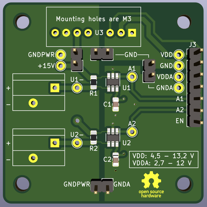
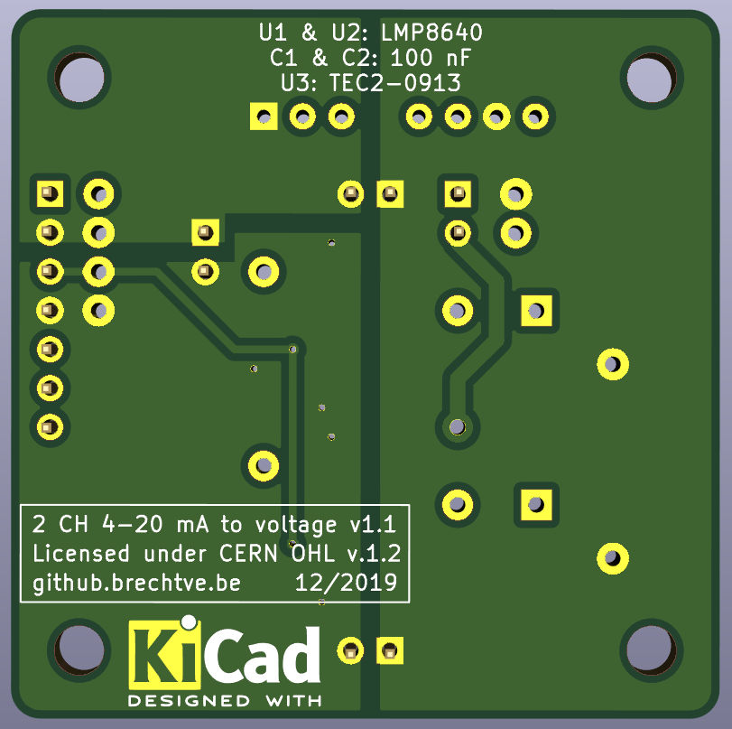
This board converts two 4 - 20 mA signals to a voltage using a LMP8640 Current Shunt Monitor from Texas Instruments. To provide power to the 4 - 20 mA sensors a TEC2-0913 2W 15V Isolated DC-DC converter is used from Traco Power. Quick-connect terminals from Phoenix Contact are also used.
To allow for extensive testing three separate GND nets/planes and a lot of test points are used. They can be connected together using jumpers if necessary. The power supply can also be disabled and fully disconnected from the sensors using a jumper as well (wich can also be used to measure the in-line current given to the whole sensor circuit).
- Click here to go to the schematic.
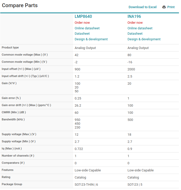
A lot of designs still use the INA196 Current Shunt Monitor from Texas Instruments. In the picture below is a comparison between the LMP8640 and the INA196. No real disadvantage was found to not use the LMP8640.
| Component | Value | Footprint | Other | Ordering |
|---|---|---|---|---|
| U1, U2 | LMP8640 | SOT-23-Thin-6 | Texas Instruments Current Shunt Monitor | Mouser.be |
| U3 | TEC2-0913 | SIP-8 | Traco Power 2W 15V Isolated DC-DC converter | Mouser.be |
| C1, C2 | 100 nF = 0,1 µF | 0805 | X7R, 16V, 10% | Mouser.be |
| R1, R2 | 6,2 Ω | 0805 | 0,1% | Mouser.be |
| R1, R2 (alt) | 4,99 Ω | 0805 | 0,1% | Mouser.be |
| J1, J2 | PTSA_1,5/_2-3,5-Z_BK | Pitch: 3,5 mm | 2 contacts @ 45° (20-16 AWG), 250V 2A | Mouser.be |
To better conduct tests with the LMP8640 chip a simple 1-CH board was layed out without a power supply and etched on a single sided board.


